Every multi-zone system comes with a small bag of parts we call the “extras” bag. These components (see photos below) are an important part of the Zone Manifold, but are not INSTALLED into the Manifold when you receive it. That’s because every installation is unique and only the installer knows whether to enter the manifold from the right side, or the left side.
Below are a series of close-up photos, detailing the parts from the “extras” bag.
-
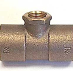
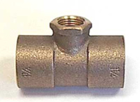
- FIP Tee – This fitting is called a FIP tee. The Zone Manifold uses several FIP’s, all the 1 1/4″ size, and various gauges and valves are installed into the 1/2″ female threads at the top of the fitting.
-
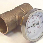
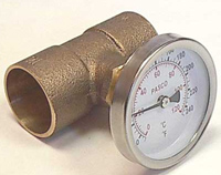
- Temperature Gauge – A temperature gauge assembly threads into a FIP tee.
-
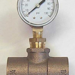
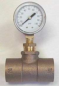
- Pressure gauge – Of course, in an actual installation, teflon tape would be used to seal the threads of the pressure gauge and the brass adaptor it threads into.
-
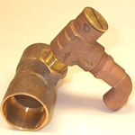
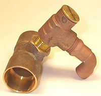
- Pressure relief valve – The pressure relief valve also threads into a FIP tee. Notice the brass cap at the top of the pressure relief valve. By removing this cap, the relief valve can be adjusted higher or lower. We pre-set the valve to “blow off” at 55-60 psi. This is ideal for most installations. The copper elbow attached to the relief valve directs any over-pressurized water safely down toward the floor.
-
- Drain valve – Two drain valves like the one shown at left are included in the “extras” bag. On both the supply side and the return side of the manifold, they are threaded into whichever FIP tee is opposite the temperature gauge. In this manner, the Zone Manifold can be drained if necessary.
-
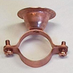
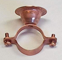
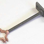
- Bell hanger – “Bell hangers” like the one shown here are used to attach the main body of the Zone Manifold to the pre-cut plywood board.
-
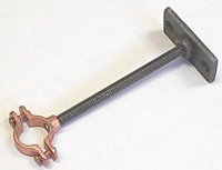
- Split ring hanger – Another mounting assembly called a “split ring hanger”. They are used to “collar” the pipe below each circulator pump.
-

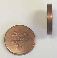
- Temporary test cap – The temporary test caps shown here should never be confused with the permanent end cap shown below
-
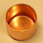
- Permanent end cap
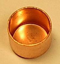
The Zone Manifold is shipped with two temporary end caps called “test caps”. These are installed in our shop to pressure test the manifold for leaks and are left on to prevent debris from entering the manifold during shipping and handling. The “test caps” must be removed before any plumbing can begin on the Zone Manifold.
The permanent cap (see above) is designed to become a permanent part of the installation. If you enter the left side of the Zone Manifold, cap the right side, and vice versa.
The Zone Manifold for Stainless pumps, complete with “extras”.
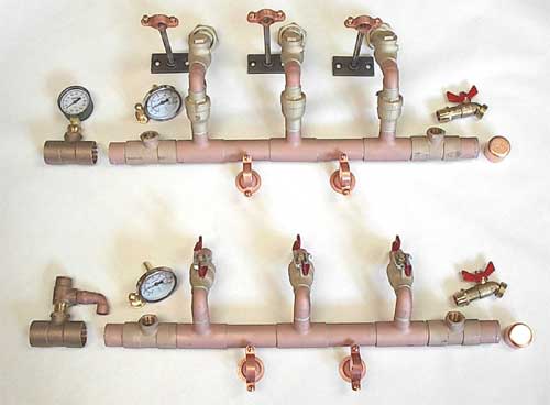
The Zone Manifold for Stainless pumps, complete with “extras”.
Note: as mentioned above, the two “loose” FIP tees can be installed on either end of the manifold. Which end depends upon how the manifold is oriented to the heat source.
The Zone Manifold for Cast Iron pumps, along with “extras”.
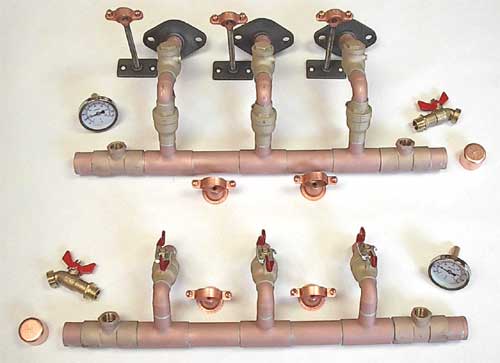
The Zone Manifold for Cast Iron pumps, along with “extras”.
Note: Because the pressure relief valve and pressure gauge are part of the Expansion and Purge Kit (always included with any cast iron manifold), the two “loose” FIP tees are not needed.
Additional Random Components
The Existing System Fill Kit
This simple plumbing array is an often neglected, but crucial, part of many hydronic heating systems. I say neglected because all too frequently a hydronic system (baseboard heaters, cast iron or wall radiators, even some floor radiant) has a valve for injecting fluid into the system at spot “A”, and a valve at spot “B” for draining (usually at a low point in the system like the bottom of the boiler). Such an arrangement can cause major problems and here’s why…
Unless “fill” spot “A” is adjacent to “drain” spot “B”, there will always be a gap in the plumbing, a gap filled with air that’s impossible to purge.
Circulator pumps are NOT powerful, self-priming pumps. They do not tolerate air and even a modest bubble can create enough resistance to stop the pumping action. In other words, it’s essential to eliminate as much air as possible from any hydronic system and to keep it purged for the life of the system.
For new “closed” systems, Radiant Floor Company includes a plumbing package called the Expansion and Purge Kit (EPK). A version of the Existing System Fill Kit, the valve assembly shown below, is included in the EPK. But for existing closed systems, many of the EPK’s components are already part of the hydronic system (pressure relief valve, air eliminator, expansion tank, etc.) and don’t need to be duplicated. So, just the “fill” and “drain/purge” valves are needed for existing systems.
-

- Existing System Fill Kit
-
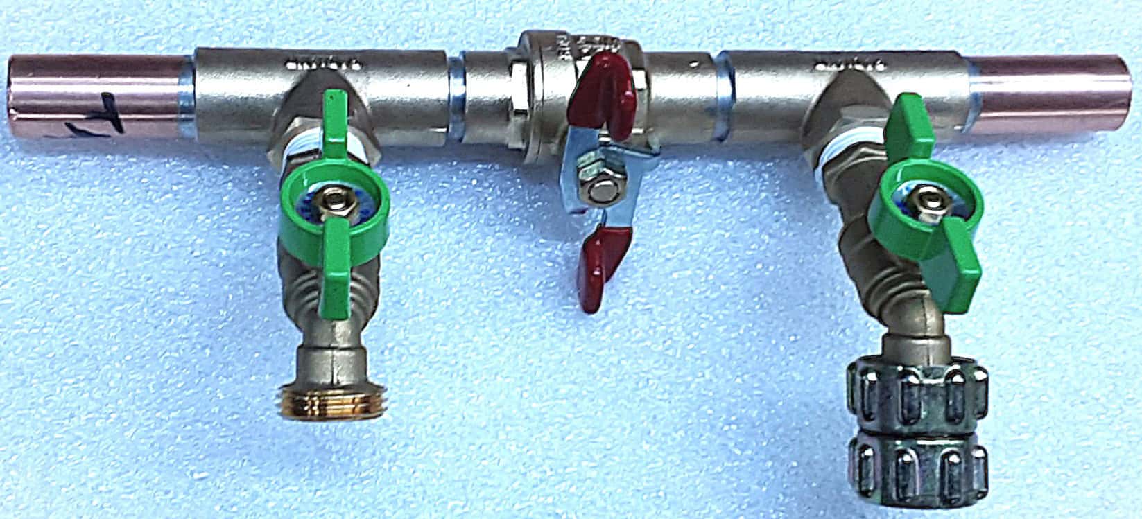
- Existing System Fill Kit
Note also the “shut-off” valve between the “fill” and “purge/drain” valve. The shut-off is equally important because the fluid must enter the “fill” valve, pass through the hydronic system, and then exit the “purge/drain” valve. Without a shut-off in between, the fluid and any accompanying air would simply spin around and around in the system. This component is designed for quick & easy installation and is compatible with “Shark Bite” style fittings.
With an Existing System Fill Kit, air has no place to “hide” in a hydronic system
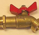
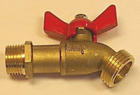
The Diverter Valve
Though not normally part of the “extras” bag, the diverter valve is worth a photo because it’s sometimes useful for, as the name implies, diverting fluid from one heating area, or appliance, to another. Basically, it’s a “tee” with a handle to send fluid either “left” or “right”.
Diverter valve
Here are two examples of useful diverter valve applications:
I have a hot tub in my radiantly heated greenhouse. But the hot tub doesn’t have it’s own heat source. It’s simply a redwood tub filled with 300 gallons of water. By using a diverter valve, I’m able to “steal”, that is, divert, fluid from my radiant floor to the “A” (anti-freeze) side of a heat exchanger, then back to the floor (though the heat exchanger has stolen so much heat, it’s barely useful for floor heating).
On the “B” (fresh water) side of the now hot heat exchanger, a small pump circulates water from the tub to the heat exchanger and back.
After a couple of hours when the tub is up to temperature, I turn the handle on the diverter valve back to its “normal” position, and the anti-freeze bi-passes the heat exchanger entirely.
Another example might be a very large solar storage tank (400 or more gallons) with an internal copper heat exchanger coil that sometimes lacks enough solar input to be useful for radiant heating. With such a huge volume of water, it may make more sense to “divert” the radiant floor loop away from the (cold or barely warm) storage tank rather than having the back-up, fossil fuel heat source inadvertently heating 400 gallons of water as it pumps fluid through a copper coil in a cold tank while in the process of heating the floors.
In other words, when the storage tank is brimming with free solar hot water, sure, let it contribute to heating the floors. But when it’s cool, take it out of the system by bi-passing it with a diverter valve.