Introduction
Table of Contents
A slab on grade is defined as any concrete slab poured over excavated soil. From a radiant heating perspective, it doesn’t matter if the slab is actually “at grade” or is poured several feet below grade as part of a full foundation. Check out our video How to Install Radiant Floor Heat Tubing in a Slab On Grade, and read this page for a full description.
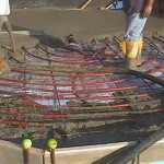
The photos below illustrate various stages of the slab on grade installation
-
- The final result will be a beautiful, radiantly heated sunroom.
-
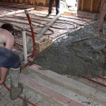
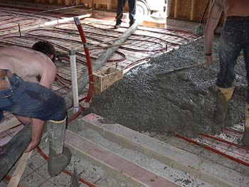
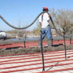
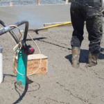
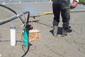
- A pumping unit was used to fill the form with concrete. The 7/8″ PEX is not delicate and easily withstands the stress of the heavy hose.
-
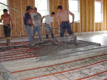
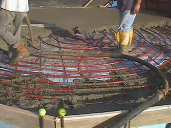
- Starting the Pour: Note that it’s okay to walk on the tubing. Just be careful with sharp tools.
The fact remains that installing radiant tubing within a concrete slab is probably the easiest, most cost effective, and highest performance application of the science. The thermal benefits are unsurpassed. Virtually any concrete pour should contain radiant tubing …even if you have no immediate plans to heat the space. After all, you may change your mind later and regret your lost opportunity. For most applications, the tubing and manifold are relatively inexpensive and the mechanical components can be installed even years later.
Of course, there are always exceptions to the rule. A woodshed or an outside storage shed with a concrete floor might be a waste of tubing. But even then you should think long and hard about the possibilities of converting these areas into heated space at some future date. I say this because often we work with people faced with the task of pouring a new slab, with tubing, over an already existing slab … and they poured their existing slab only a few years before. How much easier it would have been to install the tubing in the original slab!
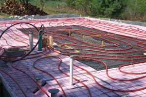
But, if you’re fortunate enough to be planning an original pour, the procedure is simple. In fact, the basics of a standard pour remain the same. The compacted aggregate base is first, followed by a 6 mil polyethylene vapor barrier, then insulation, then rebar or wire mesh, or both.
The insulation phase is crucial for a radiant floor. Mainly, heated slabs radiate outward rather than downward, so insulation on the edges of the slab is most important. Remember that your slab will be about 75 degrees F. Any cooler surface in contact with the slab will try to steal its heat. If you’re pouring up against your foundation walls, insulate between the slab and the walls. For a cleaner looking installation, cut the top edge of the foam board at a 45-degree angle so the concrete will flow all the way to the foundation wall and hide the foam.
How you insulate under the slab depends upon the severity of your winters. In lower, warmer latitudes, the 1″ XPS foam (Extruded Polystyrene foam, i.e. pink or blue board) works fine. In colder regions, use 2″ XPS.
Note the vertical insulation on the edges of the foundation. Heated slabs lose heat outward as well as downward.
Insulating a radiant slab
Detail of insulation on a radiant slab
There are many approaches to insulating a radiant slab, but the detail at right shows a frequently used method. Since the slab will be approximately 5 degrees warmer than the room temperature, a 75 degree slab is quite common. Obviously, any cooler surface in direct contact with the slab will try to steal its heat, so a thermal break greatly reduces this heat transfer.
Of course, in many situations a downward heat flow is desired as a means of creating a “heat sink” to protect the space in the event of a severe power outage or mechanical failure. A slab with such a heat sink could take days to fully cool down.
Note: Many of our customers ask us about alternate slab insulation materials like “Grid” panels, radiant foils, bubble-type insulation, and thin foams of various kinds coated with vapor barriers. Admittedly, these alternate materials have two distinct advantages over “blue”, “pink” or “purple” board, i.e. the extruded polystyrene mentioned above–they are cheaper and easier to install than multiple sheets of rigid foam.
Although pex tubing “Grid” panels may offer some ease in the installation of pex, there are a couple of draw backs when using these products. Some insulated “Grid” panel systems or modular board designs are made of EPS (EXPANDED polystyrene) foam, which may absorb moisture and lose their insulating capabilities. The most common “Blue, Pink or Purple” board, XPS (EXTRUDED polystyrene) foam is a very good insulator that does not absorb moisture. The use of these “Grid” type panels may limit tubing circuit spacing and make it difficult to maintain equal circuit lengths. “Grid” panels dictate spacing and eliminate the ability for the “adjust to fit” opportunity that regular XPS (Extruded polystyrene) foam offers. This can translate into perfectly good pex tubing being cut short and tossed away. This practice will not only short the zone of needed pex (less heat output) but now requires valve adjustment for proper equalized flow due to the uneven circuit lengths.
Reflective material is not effective in a slab (thermal mass) application, as this works most effectively in an air gap situation as you would find in a floor joist installation or for walls and ceilings. Another issue is that mineral properties of concrete (may/will) eventually degrade the foil due to electrolysis created by the dis-similar mineral/metal content, this applies to both “On grade and suspended” slab applications.
Although bubble wrap and thin foam insulation is cheap, customers report dissatisfaction with their performance when used under slabs.
For the record, Radiant Floor Company does not sell under-slab insulation of any kind. Our opinion is based on customer feedback and our own experience. We recommend Extruded Polystyrene.
So, once you’ve insulated to suit your situation, install the rebar and/or wire mesh and use rebar ties to fasten your radiant tubing to the mesh. If like most slabs you require more than one circuit of tubing, you’ll need to install a slab manifold at some convenient spot along the perimeter of the pour. The slab manifold is shipped in a plywood box that doubles as the form you pour the concrete around. Make sure the manifold box is installed plumb. Later, when the pour is complete and you unsweat the pressure test kit from the top of the manifold, you’ll want your supply and return pipes sticking up nice and straight. Install the slab manifold very near your heat source, if possible, to keep the supply and return lines from your heat source short and easy.
Our multiple Loop manifold includes ball valves for each pex circuit as this will also ensure better purging when filling the system. Equal pex lengths are the best way to ensure even balance and heating. The MOST accurate way to balance your system (with uneven lengths), is to measure the supply and return temperatures of each pex circuit. Shorter lengths will require more resistance so as to equalize flow when balancing with the longest length. The best way for properly equalized flow is equal circuit lengths.
We include (full-port) ball valves in our multiple circuit/loop, zone design. These valves are put in place for each pex circuit/loop in order to fill and purge separate lengths.
Some loop /circuit manifolds available today use Mechanical Flow meters, Balancing valves or Circuit setters. We don’t recommend them due to their stifling (flow sensing) design,… even at their “Wide Open” settings, resistance in these valves are apparent.
Mechanical Flow meters work by sensing flow via liquid movement and measures flow as the amount of fluid passing through the flow meter. This movement is metered through a resistance design, which inhibits flow and increases resistance/head pressure. Another disadvantage of mechanical type water flow meters for water measurement is that they may clog more easily when the liquid is dirty, contain particulates and create increased flow restriction etc. This can lead to increased maintenance issues. Mechanical water meters also do not work well when the water flow is low. The zone’s pump may not overcome this head pressure due to the resistance created by this resistance. There may (then) be a need to up-size the zone’s pump, OR the supply and return line’s size may be increased to lessen this (potential) issue. The pump size / model for each zone is dictated by the zone’s volume and supply and return piping,…This is based on using 3/4″ copper for zones with multiple circuits larger zones volume may require 1″ supply and return, again total zone volume will dictate this requirement. Each type of flow-meter has its own specific applications and installation constraints. There is no “one size fits all” flow-meter.
Our findings support the a-fore stated information and is based on years of shop and field experience as well as customer feed back through diagnosed troubleshooting.
Depending upon which size tubing you’re using (7/8″ PEX or ½” PEX) you’ll space the tubing either 16″ on center, or 8″ on center respectively. Keep in mind that while you’re looping the tubing back and forth, up and down the slab and so forth, you won’t be trying to make a 16″ bend in the tubing. The actual bend will probably be closer to a 24″ radius….depending upon whether you’re installing the tubing on a warm summer day, or a cool fall evening. In other words, warmth equals flexibility. But whatever the temperature, just allow the tubing to conform to its natural bend. You may want to experiment with a 4 ft. piece of tubing before you start. Slowly start bending until you reach the kink point. That will give you some idea of how tight your bends can be. Then later, while laying out your circuits, and after your wide, comfortable bend, you can begin spacing the tubing roughly 16″ on center on the straight-away’s (8″ on center for 1/2″ PEX).
Radiant Floor Company’s Pex tubing has a dimensional mark every 5 feet so that you’ll know the length/position you are, at that point in the roll, as you lay the Pex tubing out. When you are near 40′ to 50′ (of the return end) away from the loop manifold, it is a good idea to make the return connection to the loop manifold, then work the Pex back, so as not to run short, or long when you reach the length’s end. Running the Pex in this manner will also insure equal lengths, when the final (return) connection of each Pex loop to the manifold is made.
-
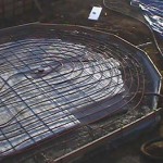
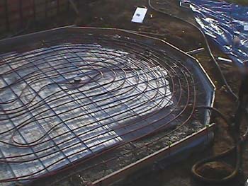
- “Heat sink” slab installation
-
- “Heat sink” slab installation
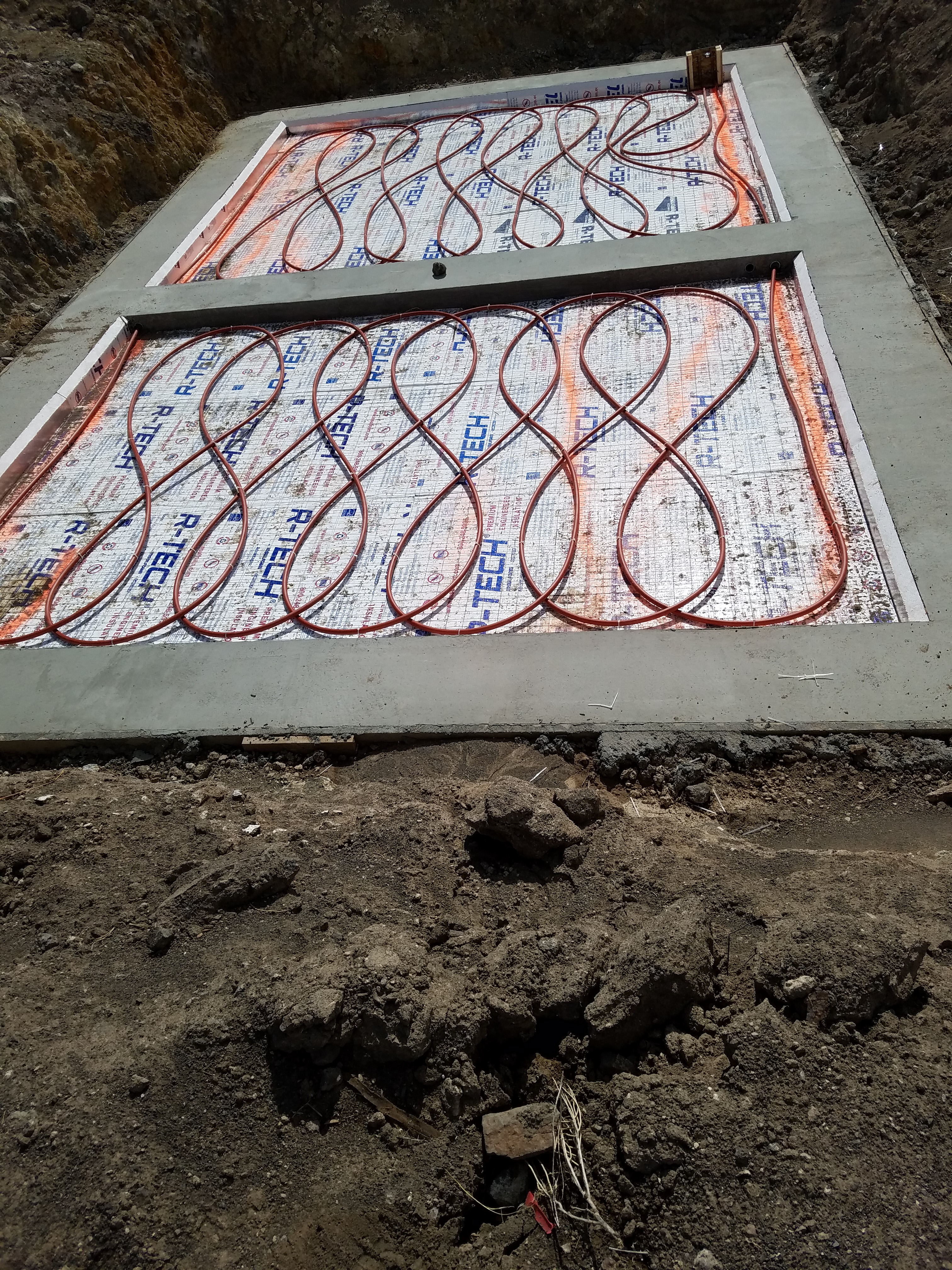
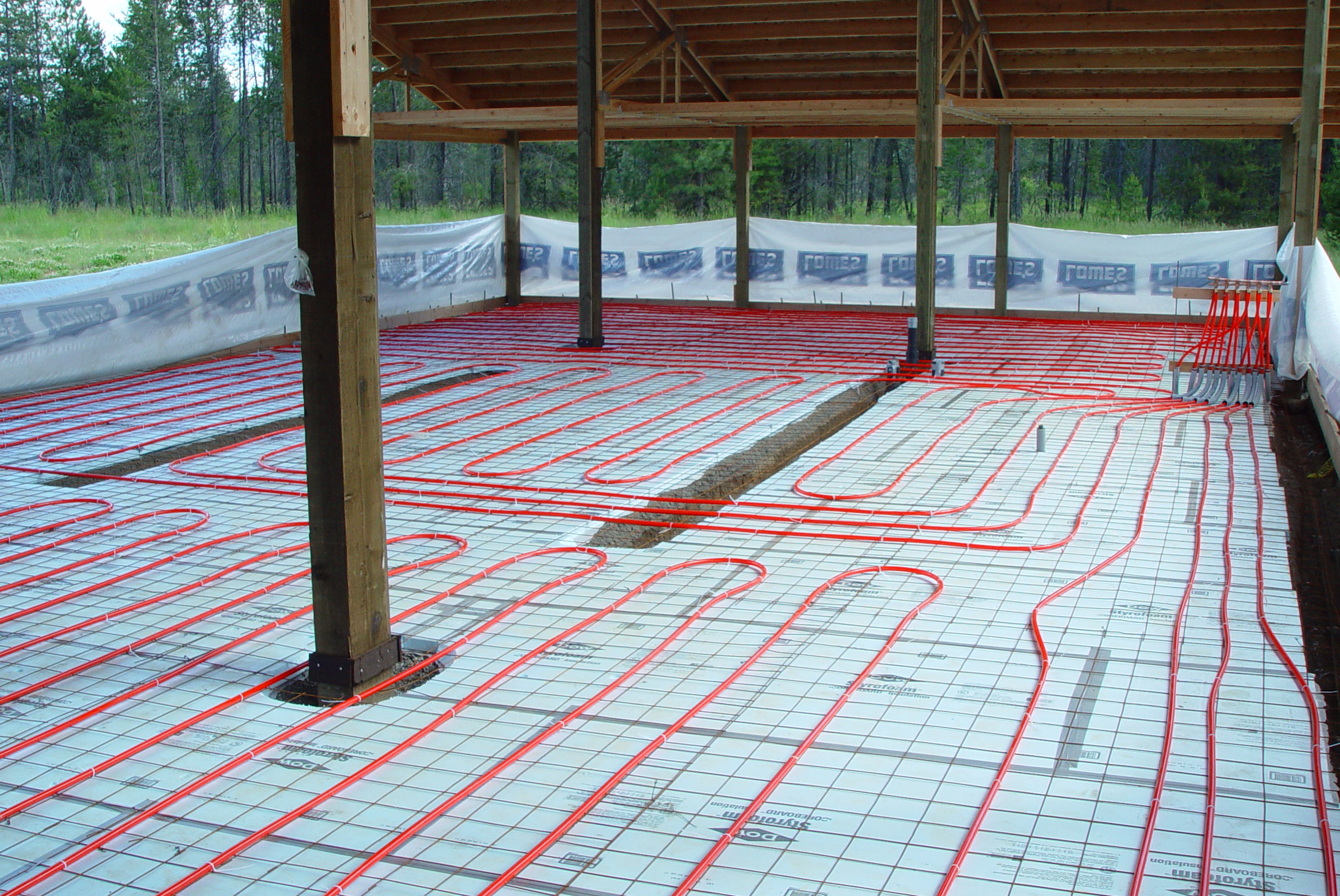
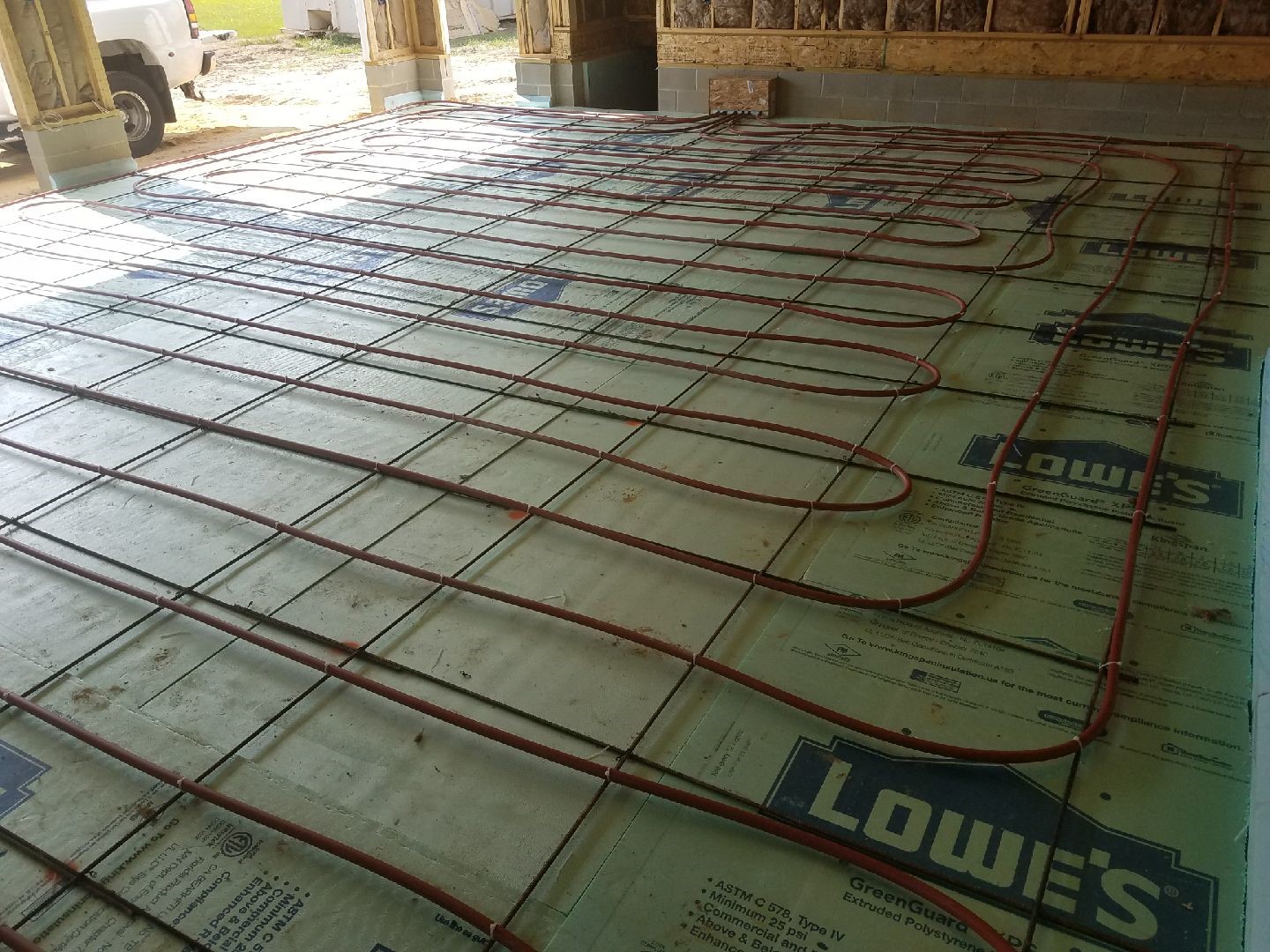
The two slab installations above use 7/8″ PEX tubing, 16″ on center. Notice the wide, comfortable bends, then the 16″ on center spacing on the straightaways. Both of these installations utilized the “heat sink” option, i.e. the central 30% of the slab was left uninsulated. In areas prone to long power outages, this approach can give the slab a very long “thermal swing” by storing heat in the mass below the slab. Large thermal mass protects the home from freezing even after days without a heating system.
Future workshop slab prepped with insulation, wire mesh, and 7/8″ PEX.
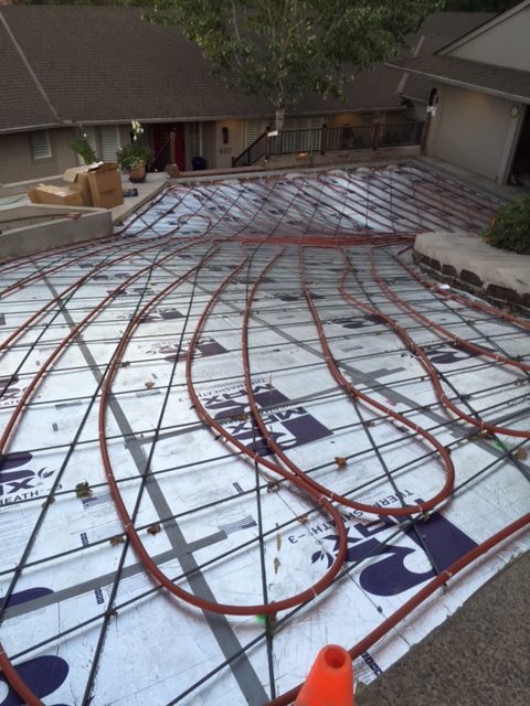
Loop the tubing in any convenient pattern, maintaining the proper spacing. Come in about 6″ from the perimeter. It’s okay to cross the tubing as long as you don’t create a tubing stack so thick it threatens to rise above the surface of the slab. You can see how that wouldn’t be a great idea!
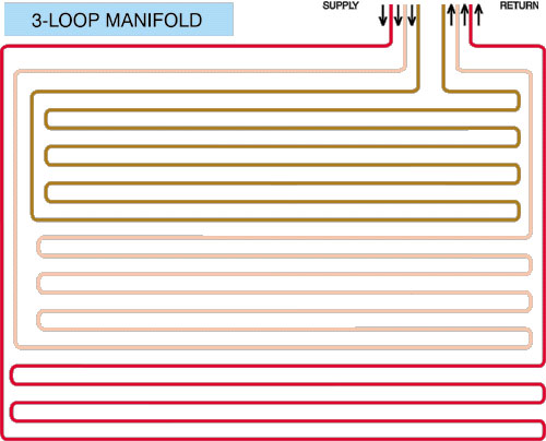
Three-loop manifold system
The three-loop system pictured here is a commonly used layout pattern for a typical slab on grade installation.Although it’s perfectly okay, and sometimes necessary, to cross one tube over another during tubing layout, notice how this simple configuration places each loop within its neighbor, starting from the outer connections of the manifold and working toward the center.
Once the tubing is run, and all the connections are made to the manifold, replace the front cover of the manifold box and pressurize the system to 50 PSI. Wait several hours or overnight. Sometimes the air in the tubing cools down and a few pounds of pressure are lost. However, if the gauge indicates more than a 5-PSI drop, check for leaks in the tubing. Most of the time, the connections to the manifold just need a bit more tightening. If that doesn’t solve the problem, inspect the tubing for signs of damage. A sharp piece of wire mesh may have punctured the tubing during installation. It’s rare, but it can happen.
If a puncture is discovered, use a repair coupling, or if that method offends your sense of perfection, replace that circuit of tubing. In most cases, replacing a complete circuit will cost less than $200. It will cost only pennies if you can cut out the damaged section and reuse the tubing later in a floor joist application.
It is also a good idea to stuff some scrap foam, newspaper, an old rag, or whatever, around the tubing where it enters the manifold box. That way, if your concrete is unusually soupy, it won’t be able to flow into the box and touch the copper manifold.
Once the system has been tested and proven free of leaks, lower the pressure to 25- PSI. With the gauge at 25-PSI, you’ll have a visual indication that the system is holding pressure during the pour itself. Should that pressure drop, find the source of the leak and either use a repair coupling, or form around the damaged area and repair it later.
Just remember that damage during the pour is rare. The tubing isn’t delicate and in most cases is spaced 16″ apart. There’s plenty of space to walk between the tubing runs. If concrete needs to be wheeled across the floor, simply lay down some plywood planks to spread out the weight and protect the tubing.
And while we’re on the subject of pre-pour preparations, this would be the ideal time to install the “sensor sleeve” if a floor sensor is being used to control the zone instead of the standard wall mounted thermostat.
The “sensor sleeve”
The “sensor sleeve” installed in the manifold box
Briefly, a floor sensor is a small thermistor that monitors the actual floor temperature instead of the air temperature in the zone heated by the slab. It’s the preferred method of control if a second heat source contributes heat to the zone. A radiant zone with a frequently used wood stove would be a common example. A forced air duct blowing into the radiant zone would be another. Obviously, if air temperature controlled the radiant floor, it would never come on when these other heaters were activated. The air would be warm, but the floor would stay cold.
With a floor sensor controlling the radiant zone, independent of the room’s air temperature, the floor maintains whatever baseline temperature you desire and the other heat sources, if used, can make up the difference.
So, when installing a floor sensor thermistor, never embed the thermistor itself into the concrete. Instead, take a ten foot piece of PEX tubing, plug one end, and embed this “sensor sleeve” into the slab. Later, you can feed the thermistor into the embedded tube. This will guarantee future access to the thermistor and make replacement an easy matter.
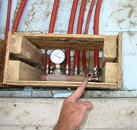
Pressure testing assembly
Pressure testing assembly 5 loop manifold
Once the pour is completed, the pressure testing assembly you see here is removed. Using a soldering torch, simply unsweat the top section of the manifold and discard it (be sure to bleed off any pressure within the manifold beforehand). This will leave two vertical pipes sticking up above slab level…your supply and return lines. The connections themselves remain below slab level within the “manifold well”. They are fully accessible, untouched by concrete, and protected from possible damage during future construction.
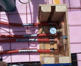
The photo above on the right shows a different job with the slab manifold buttoned up and ready for the pour. Note the fiberglass insulation stuffed around the tubing. Scraps of foam, newspaper, or rags will also serve to keep concrete from flowing into the box and touching the copper manifold.
Pressure gauge
This system was pressure tested at 50 psi, but lost about 3 psi after hours. This is common and results when the air cools in the tubing, especially overnight. However, if the pressure drops more than 5 psi over the same time period, check for leaks. Most often, the connections simply need tightening.
Pouring the slab
-
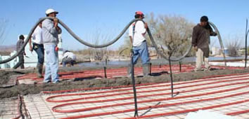
- Moving a concrecte pumping unit over an installed radiant system
-
- Pouring the slab around the manifold box
-

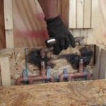
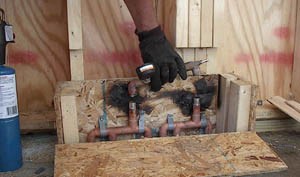
- Removing the pressure assembly with the manifold box in place
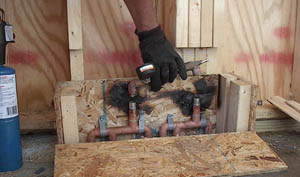

The Manifold After The Pour: When the box is broken away, a ‘manifold well’ has been created. This well keeps the connections visible and accessible, but safe from damage during future construction. If the tubing were sticking up out of the slab, the chances of harm coming to the exposed PEX pipe are much greater. Notice also how the pressure test kit bridges the supply and return side of the manifold. This temporarily creates a closed loop, allowing the system to be pressurized. When the manifold is ready for final connection to the heating system, the test kit is either cut off or unsweated, leaving only the two vertical supply and return pipes sticking up above slab level.
When using a concrete pumping unit, it’s best to hoist the hose, rather than drag it across the tubing. This is especially true when the concrete company creates a long hose by coupling together shorter sections with a heavy steel fitting that can crush or puncture the tubing.
The following procedure relates to both “Boxed” Loop manifolds in slab and “Wall Mount” designs:
When you’re ready to connect the Slab/”Loop” manifold to your system component (Zone manifold or Radiant Ready), the pressure testing assembly is removed. It’s a good idea to unsolder the pressure assembly before the manifold box is cut away and discarded. That way you can use the box to shield the wall behind it from the effects of the torch. Bleed the air pressure from the loop manifold (at the schrader / valve stem), heat and un-solder both of the elbows on the pressure assembly. The two copper stubs (then) become the “Supply & Return” loop manifold connections. Clean and prep the stub connections, as these two pipes will plumb to the supply and return of the Zone manifold (for a multiple zone system) or “Radiant Ready” (for a single zone system) connections.
-
- Example of “Boxed” loop manifold
-
- Example of “Wall mount” loop manifold
-
- Another “wall mount” example
-
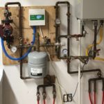
- A boxed loop manifold with completed connections
-
- Large zone “wall mount”design
-
- Loop manifold with alternating supply & return
Connecting multiple slab manifolds

Multiple slab manifold schematic
With a single zone in a very large slab it is usually better to gang together multiple slab manifolds and spread them over the zone rather than create a single monster manifold that forces all the circuits to begin and end in one location. This more spread out approach eliminates the unwieldy cluster of stacked tubing that is the inevitable result of the single mega manifold.
Though not the easiest way to manifold slab circuits, occasionally an installer will run the return side of a slab circuit adjacent to the supply side. In other words, instead of having all the supply ends on one side of the manifold and all the returns ends on the other, the tubing will alternate across the manifold like this: Supply, return, supply, return, supply, return, etc.
We normally come across this approach when the tubing has been installed alone, i.e. without any manifold at all (and without the benefit of a pressure test before the pour) and the customer needs to connect multiple circuits long after the concrete pour.
Obviously, this situation can present some difficulties. First off, unless each circuit is clearly marked, the person plumbing this zone will have to determine which of the random tubes sticking out of the slab are “supplies” and which are “returns”.
This forces the plumber to blow air into tube #1, and then determine from which of the other tubes it escapes. Hopefully, the plumbing person has a handy air compressor available. Otherwise, they’re left with the absurd task of blowing into multiple tubes, all hundreds of feet in length, one by one, and labeling as they go. This is not only tedious for the plumber, but potentially embarrassing for onlookers with vivid imaginations.
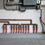
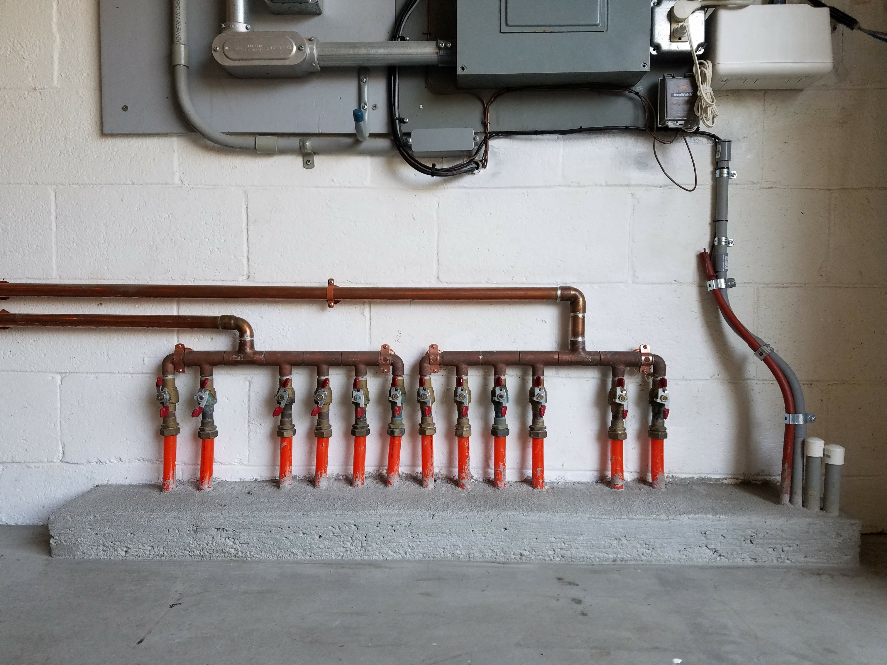
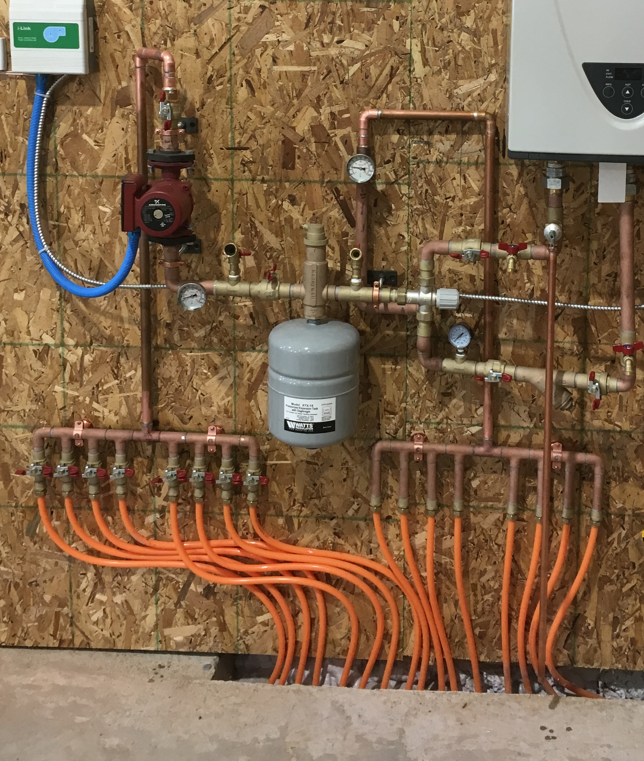
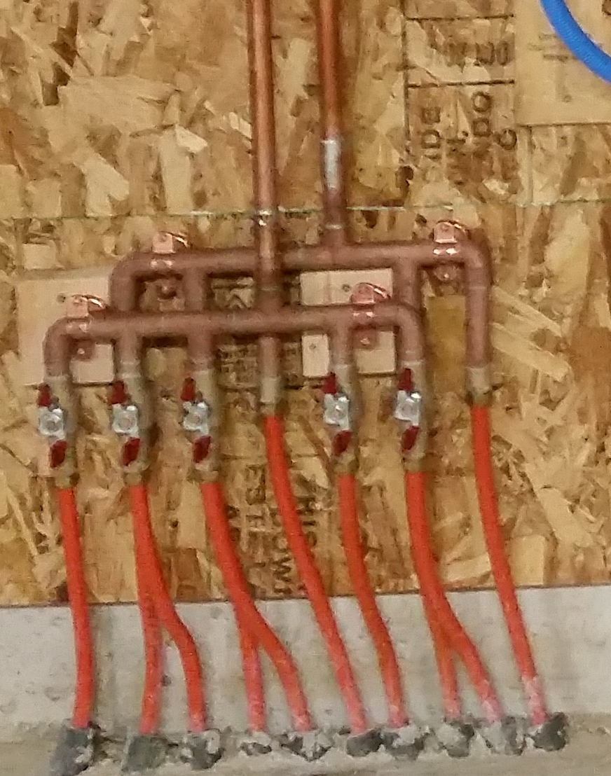
Front to Back wall mount manifold
So, the above is an example of what we call a front to back design manifold. It manifolds supply (red ball valves) and return lines (adaptors only) that have been installed side by side. The point is, Radiant Floor Company can accommodate any circuit arrangement for any slab zone.
Snow melt
Fact: Melting snow and ice with radiant heat consumes a staggering amount of energy. Simply imagine a warm mass of concrete or asphalt exposed to the elements and pouring BTU’s freely into the atmosphere and you’ll understand what we mean. Only a massive, and very expensive, solar powered snow melt system would avoid this almost embarrassing fossil fuel consumption. Plowing and shoveling may be harder, but they’re a lot cheaper and certainly more environmentally responsible.
However, having said that, some special situations can make snow melt justifiable. One of our customers, for example, used snow melt to keep a set of outside concrete steps, on an attached apartment, safe for his 81 year-old mother. Another customer bought a house and discovered during his first winter that, thanks to poor design on the part of some contractor, dangerous ice sheets formed on heavily traveled areas around his badly graded driveway. In these situations, the need for safety justifies the enormous energy consumption (and expense) of radiant snow melt.
Here are a few guidelines:
First, always install a 6 mil polyethylene vapor barrier, then insulate as much as possible under and around the snow melt area. Snow melt is difficult. Direct the energy toward the task of melting the snow instead of leaking thermal energy into the ground or to the surrounding air. The vapor barrier prevents moisture from migrating up from below and stealing heat from the tubing.
Second, use a spring timer to activate the system instead of a thermostat, slab sensor, or some high-tech snow detection system. A spring timer with a maximum 12-hour range will eliminate the possibility of leaving the snow melt running when it’s not needed! The spring timer requires manual activation of the system, and then winds down to “off”.
Experience soon teaches the homeowner how to manage the system’s energy consumption based on local weather forecasts, features, and conditions. The spring timer itself should be fed power via a standard light switch. In this way, if you crank the snow melt “on” for five hours, but notice that the snow has melted after three hours, the timer can be manually switched off. Some customers take the further step of wiring a light bulb into the same circuit to give the operator a visual indication that the snow melt is operating. Again, these are simple, effective ways of preventing the snow melt system from ravaging your energy bill. Believe me, you don’t want to be heating your driveway four days after the last snowstorm.
Third, as indicated by the drawing below, always encase the radiant tubing in a compacted sand bed and always pump cold water through the tubing while applying the asphalt. This will literally prevent the tubing from melting. The compacted sand increases the thermal mass of the system for maximum performance and also protects the tubing from damage during application of the asphalt.
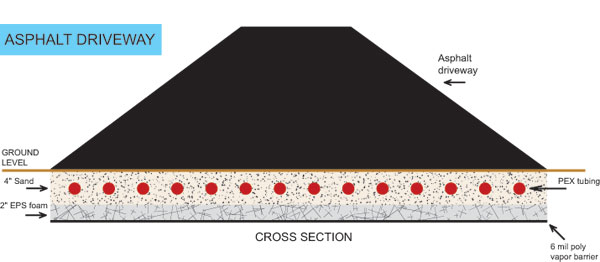
Asphalt Driveway Cutaway
And speaking of asphalt, always “cap” the asphalt with the appropriate sealer. Without the proper topping, the melted snow simply absorbs into the unsealed driveway and leaches heat away from the radiant tubing. In effect, the snow melts into microscopic puddles of water instead of flowing away from the driveway. All this liquid must then be “steamed off” by the snow melt system. Of course, this scenario assumes that the system is capable of generating enough heat to evaporate a driveway of saturated asphalt. Not likely. Even a well designed snow melt system would have to squander energy twenty-four hours a day to pull that off.
A snowmelt parking area and driveway, well graded for drainage
Fourth, if possible, in the case of new construction, orient driveways and walkways to take advantage of natural solar radiation. This may include removal of selected trees to prevent shading or adding a dark shade of integral dye to a poured concrete driveway. Do whatever it takes to gain some solar assistance.
Fifth, always provide adequate drainage. After all, why create dangerous ice sheets with melted snow? A properly graded driveway or walkway should channel the water away to a safe location. This prevents the inconvenience of snow from mutating into a disaster of ice. Proper grading also means no low spots (i.e. puddles, then ice patches) on the driveway itself.
When The Unthinkable Happens
Oops!…..your concrete contractor forgot to install a key anchor bolt into your slab pour. He returns the next day with a masonry bit and a 1/2″ hammer drill, then tries to remedy the error by drilling a hole in the new slab…..and, well you guessed it. He drills right into your radiant tubing. What do you do now?
Well, after you calm down (generally sometime between hiding his body and returning to the job site), you begin the arduous process of chipping away the concrete and installing a repair coupling. You’ll need to create some wiggle room because the tubing has to be flexed enough to work the repair coupling securely onto both open ends of the PEX without kinking and further damaging the tubing. Four to eight inches on either side of the affected area is probably about right (see photo below).

The approximate amount of concrete that should be chipped away to effectively repair tubing damaged in a hardened slab.

Self-vulcanizing rubber tape protects the brass coupling from direct contact with the concrete.
Then, carefully cut out the damaged section with a PVC cutter. You can cut out about 1/2″ of tubing and still have plenty of PEX to make a very secure connection.
The final step involves wrapping the coupling with self-vulcanizing (sticks to itself) rubber tape or vinyl tape. This prevents the concrete from coming into direct contact with the brass coupling and this procedure should be used ANY time a coupling is used in a concrete pour.
When to use twice the normal amount of tubing
When you’re installing a radiant floor in high heat loss areas such as poorly insulated homes or modern dwellings with lots of glass and high ceilings, it’s often necessary to double up on your tubing. In the case of 7/8″ PEX, normally installed 16″ on center, the tubing should be placed 8″ on center. The proper method of doing this is to run the PEX as you would normally, 16″ on center on the straight-away’s, and a nice comfortable 24″ radius on the bends. Then, when you’ve covered the entire zone, simply repeat the process from the beginning. This way you’ll end up with two runs of tubing roughly parallel to each other, about 8″ apart, but you won’t have to attempt an impossibly tight bend to do it.

Even a warehouse this large can be a single zone. The secret is multiple, even circuits of tubing