Introduction
Contents
Radiant heat is actually an old technology. It’s common knowledge that the ancient Romans used it to heat their public baths. In more modern times, the Europeans have relied upon radiant heat for over 60 years. In fact, it was servicemen returning from World War II who first spread the word about under floor heat to their fellow Americans. Many radiant floors, most using copper tubing buried within concrete slabs, were installed and used successfully in the 1960’s and 70’s. But they all suffered from one primary problem…longevity. Copper within concrete is highly susceptible to corrosion and a life span of 50 years for a radiant floor was considered exceptional. Today, modern plastics not only share many of the heat emitting properties of copper, but also provide greater flexibility, corrosion resistance, and a life span of over 100 years.
Pex is a standard “Industry” product, with a multitude of uses. “PEX” is an Acronym for “Poly-Ethylene”, that is “Cross-linked”- (X) = ….”P E X“!
“Pex” tubing begins as Polyethylene, a derivative of Natural Gas. It is then processed into the form of pellets, these pellets are later melted down and run through an “Extruder”. This is known as the “Extrusion process”, the process by which polyethylene tubing is created. “Cross-linking” alters the molecular structure of the tubing. Once completed, this change strengthens the tubing (now Pex), enabling greater pressures and higher temperatures.
Polyethylene is a highly useful and common material that is most often utilized in the making of milk and water cartons (and many other food item containers). There are three cross-linking processes. The first two (most common) types of cross-linking are “Peroxide” (type-“A”) and “Silane” (type “B”), these are chemical cross-linked Pex. The third process is known as “Electron beam” (Type “C”) Electron beam Pex.
Radiant Floor Company’s Pex tubing (type “B”) is suitable for domestic applications.
Oxygen Barrier Pex is “Pex” with an outer coating, designed to eliminate / minimize oxygen permeation, aka “Oxygen diffusion”. Although studies indicate that if water temperatures remain below 140 degrees, no significant amount of “oxygen diffusion” will occur…. For Closed Radiant heating systems, certain boiler manufacturers simply require oxygen barrier Pex tubing (in Closed radiant heating systems) for warranty purposes. This despite the fact that none of the experts seem to agree on how much, if any, damage is being done to the radiant system. As mentioned above, at normal, low radiant temperatures, oxygen diffusion is minimal. Is it worth spending more on tubing in order to, maybe, prolong the life of the system? Especially since non-barrier tubing has been used for years in low temperature systems without any reports of accelerated damage. Although we do offer Barrier pex, we’ve seen no ill effects in any of our Radiant heating systems,..Open or Closed,…with or without Barrier pex.
Of these modern plastics, polyethylene is by far the best and most commonly used material. Below is a photo of our most versatile and highest output tubing. With 7/8″ PEX you can expect a heat output of at least 50 BTU’s per foot in a slab on grade installation and 40 BTU’s per foot in a floor joist application. Our 7/8″ PEX includes ultraviolet resistant for protection against sun damage during installation. It is available as either a standard PEX tubing or as a PEX tubing with an oxygen barrier.
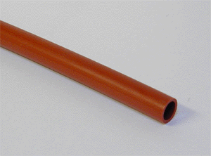
Radiant Floor Company 7/8″ PEX
The 7/8″ PEX is a large diameter tubing, made in America, and with the same wall thickness as the commonly used 1/2″ PEX. It’s main advantage over 1/2″ PEX lies in the fact that it holds more fluid, and consequently, more heat. It has a slightly lower temperature and pressure rating than 1/2″ PEX, but it can be spaced as far apart as 16″ on center and still heat a room insulated to modern standards (R-19 walls, R-27 ceilings). It would take twice as much 1/2″ PEX to do the same job.
That makes 7/8″ PEX the first choice for any application where it can be feasibly used. It is ideal for joists bays spaced 12″, 16″, or 24″ on center, or virtually any slab on grade installation. It is the only cross-linked 7/8″ PEX tubing on the market and its bending diameter is less than 20″, making it easy to thread through floor joists. This flexibility factor makes 7/8″ PEX much less prone to kinking than other 7/8″ Poly tubing. Also, minimum tubing is required to gain maximum heating results. That saves money on materials and time.
It’s also important to remember that all plumbing systems, whether for domestic hot and cold water or hydronic heating, are subject to various environmental factors. The water’s mineral content (“hard” or “soft” water), PH (acidic or alkaline), and additives like chlorine can all affect the copper, galvanized, or plastic components in domestic water systems, including PEX tubing.
And although cross-linked polyethylene (PEX) is among the most durable of all these components, there are circumstantial reports that high concentrations of chlorine, in a tiny fraction of cases and specific to municipal water supplies, may have degraded PEX tubing. This can potentially affect “open” radiant systems supplied by municipal water departments.
So, if you have reason to believe that your municipal department treats the local water with higher than normal degrees of chlorine (4PPM), you may want to consider a “closed” or “heat exchanger” heating system. Both these system types allow the homeowner to charge the radiant system with any water they choose (distilled, or spring water, or water from some other low mineral or non-chlorinated source).
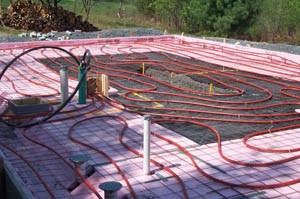
7/8″ PEX tubing in slab on grade layout, 16″ on center
The 1/2″ PEX is also a polyethylene tubing with a very high temperature and pressure rating (180 degrees at 100 psi). It emits about half the heat of the 7/8″ PEX, but its bending diameter is tighter. Using 1/2″ PEX for small zones and tight crawl spaces makes sense. It has a bending diameter of 15″ and should be spaced 8″ on center.
Various other types of tubing such as rubber, soft copper, polybutylene, or even plain, so-called “High Density Polyethylene” (not cross-linked) are used for radiant heat. But the limited longevity of rubber, the difficulty and expense of installing copper, past problems with polybutylene, and the tendency of plain, “High Density Polyethylene” to shrink and crack in high temperature applications, make PEX the tubing of choice for most applications.
Of course, regardless of which type of tubing is used for your radiant system, consult with your local building department to guarantee conformity with local codes. (return to top)
What is Cross-Linking?
According to the Radiant Panel Association, cross-linking is:
“a three dimensional molecular bond created within the structure of the plastic which dramatically improves a large number of properties such as heat deformation, abrasion, chemical and stress crack resistance. Impact and tensile strength are increased, shrinkage decreased and low temperature properties improved. Cross-linked tubes also have a shape memory which only requires the addition of heat to return it to it’s original shape when kinked“.
The Oven Test
If you’d like to see a graphic demonstration of how cross-linked Polyethylene differs from non-cross-linked Poly tubing, see the photos below.
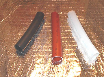
Polyethylene vs. Durapoly
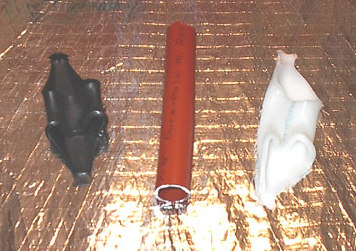
Tubing after the Oven Test
The tubing on the left is black because the Polyethylene contains a 2% carbon element for ultraviolet protection. The milky tubing on the right is a 7/8″ ID “natural” Polyethylene. It is not cross-linked, nor does it contain the pigment necessary for ultraviolet resistance. The 7/8″ PEX in the middle is both cross-linked and UV protected.
The cross-linking process greatly increases the pressure and temperature characteristics of the Poly tubing. When all three tubes were subjected to 30 minutes of 250 degree temperatures, only the PEX survived the experience. (return to top)
Heating Your Water
![]()
![]()

![]()
![]()
![]()
Radiant Floor Company pioneered the use of on- demand / tankless water heaters for radiant floor heating nearly 25 years ago when many in the heating industry believed that “on-demand / tankless water heaters would never work for radiant heat”…we disagreed! We’ve been doing this longer than anyone, with great success!
**Fuel Source Comparisons: Let’s say for instance”1000″ square feet, using “Good” insulation (R-19 wall / R-27 ceiling with 0 degree (outdoor temperatures) will result in a heat loss of approximately 24,500 BTUs per hour,… 0 degree outside while maintaining 70 degrees (inside), will require24,500 BTUs,…..(divided by *85,500) = .27 ± gallons of propane per hour at those parameters. The a fore mentioned parameters are extreme and worst case scenario, but it does give you an example of how fuel consumption may be figured.
A Kilowatt (1000 watts) translates to 3,413 BTUs,…. A gallon of propane can produce 90,600 BTUs,….. A Therm (100 cubic feet) of Natural gas, is equal to (approximately) 100,000 BTUs. And 1 gallon of heating oil represents (about) 135,00 BTUs.
Using the previous equated numbers, The following examples are illustrated for comparison:
Propane: 24,500 BTUs translates to .27 gallons of Propane.
Electricity: 24,500 BTUs translates to 7.2 kilowatts (7.2 kw X 3413 btu= 24,573).
Natural Gas: 24,500 BTUs translates to .25 Therm (One therm / 100 cubic feet) ( .25 X 100,000 btu= 25,000).
Oil: 24,500 BTUs translates to .18 gallons of Oil (24,500 divided by 135,000= .18).
The previous results are “Input” numbers, prior to an appliance’s energy rating. “Input” Multiplied by the appliance’s “Efficiency”, equals that unit’s “Output”.
EXAMPLE: 100,000 BTU (input) X 95% (efficiency) = 95,000 BTUs “OUTPUT”. Propane provides approximately 90,600 BTUs per gallon…X 95% (Heating unit’s efficiency) = *85,500 BTUs per gallon. Altitude will lessen a unit’s efficiency. De-rating a unit’s output must also be figured per manufacturer’s specifications.
Altitude Effects: De-rate 4% per 1000 ft. of altitude starting at 3000 ft., but include the 3000 ft. in the de-rate.. Applies to both propane and natural gas. This can affect the efficiency slightly (1% to 2% up or down) depends on the equipment. Consult manufacturer’s specifications for greater detail.
The end result energy usage cost can be figured once the price for each fuel type is realized,… Price per gallon of Propane, Oil, Cubic therm of Natural Gas, or Kilowatt will vary by region etc.
Electric units (technically) are the most efficient heating units. Standard tank type electric water heaters suffer from slow recovery rates, but electric on demand water heaters and boilers don’t. For large radiant systems, a 100-200 Amp service panel is dedicated to the heat source. But, if rates in your area are low, electric water heating may be cheaper **Refer to Fuel Source comparisons above. Since electric units don’t require venting, no BTU’s are dumped up a flue stack. That translates into 100% efficiency.
As long as the water flowing through the tubing is a steady temperature between 120 and 135 degrees, the method of heating it is up to the homeowner.
Tankless / on demand water heaters heat water only when needed, resulting a most efficient gas water heater. Tankless / on demand water heaters can be up to 34% more efficient than tank water heaters.
Radiant Floor Company tankless / on demand heaters are “DESIGNED & RATED FOR SPACE HEATING”! These units are not your “typical” water heaters, so don’t let the compact size fool you! All of our heating units are manufactured to an industry standard of quality and reliability.
These highly efficient heaters are built with Radiant heating in mind. We offer units that will heat both your Radiant (space heating) and domestic hot water. Regardless of which radiant heating system you choose, be it Open, Closed Or combination/heat exchanger, or type of fuel source you require, Propane, Natural gas, Electric or Oil,…Radiant Floor company has you covered!!!
So what is the easiest, most efficient way to make hot water? The answer depends upon your needs. If the combined requirements of both your domestic hot water and space heating needs are less than 200,000 BTU’s then a domestic water heater can do the job. Just remember that not all water heaters are created equal. Some are specifically engineered for domestic and space heating applications. A water heater purchased from your local hardware store may very well do the job…as long as your BTU requirements are low. But the cost of running such a unit may be alarming. Until recently the efficiency of many water heaters has been as low as 60%. That means that a full 40% of your fuel costs are going up the flue stack. The long-term result is enough wasted money to pay for a high-efficiency water heater…but you won’t own one! It’s always better to search the market for the best water heater you can afford and size it for your heating requirements.
On the other hand, if your home uses a combination of baseboard radiators and radiant heat, a situation common to retrofit projects, a boiler may be your best bet. Boilers are designed to deliver lots of heat energy. They heat relatively small amounts of water to very high temperatures and vary in size from about 100,000 BTU’s to as high as you want to go.
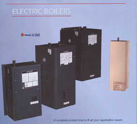
Other options include indoor and outdoor wood boilers, ground source heat pumps (sometimes called geothermal heating systems), electric boilers (if electricity in your region is inexpensive), and increasingly, on-demand water heaters.
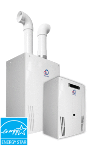
Navien condensing On demand / tankless water heaters provide High efficiency (up to 0.96) These units are manufactured with long lasting, durable stainless steel heat exchangers and include many excellent features. They’re extremely well engineered, quiet and compact. These units are wall mounted & vent with 2″ PVC for both intake and exhaust. All models virtually eliminate “stand-by” heat loss. Detailed information and specifications for these units can be found by following this link: https://www.navieninc.com/residential/tankless-water-heaters

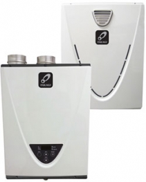
A.O. SMITH / Takagi tankless / on-demand water heaters have many excellent features. They’re extremely well engineered, quiet, compact (2.2 cu. ft.), lightweight (60 lbs.), can mount conveniently on a wall, vent easily, are “direct vented”, meaning they use outside air for combustion, and use 3″ PVC for both intake and exhaust. All models virtually eliminate “stand-by” heat loss. In other words, they don’t store hot water, they heat water only when you actually need it.
The only electrical connection to the On Demand / Tankless water heater,… is the power (plug) to/from the unit. The water heater is triggered when the unit senses a minimum of 1/2 gallon per minute of flow. The water heater activates when any or all zones call for heat and the pump(s) circulate liquid through the unit, thus creating the “flow” that signals the water heater to fire up!
-
- Takagi TH3

-
- Takagi On Demand water heater
Unlike standard, tank-type water heaters, on-demand units eliminate “standby loss” by heating water only when you need it. This feature alone can save up to 10% on fuel costs because standard water heaters leak heat to the surrounding air 24 hours a day. Electronic ignition eliminates the wasteful pilot light common to standard water heaters.
In addition, on-demand heaters are lightweight, install in tight spaces, provide limitless hot water, and the most sophisticated brands, like Takagi, monitor inlet water temperature and modulate the heater’s burner up or down for maximum energy efficiency. A digital display indicates incoming and outgoing temperatures, flow rate, flashes error codes for troubleshooting, and allows the user to set the unit for a variety of different temperature settings. Maintenance is simple – basically the fine-mesh inlet screen that should be checked periodically and kept clean.
Note: New installations may require daily cleaning until soldering flux and minor debris has been screened from the system.
Another excellent option is solar energy. With fuel prices rising, solar water heaters are not only clean, efficient, and environmentally sound, but they deliver years of service long after they have paid for themselves. Radiant Floor Company can design a solar system to meet your needs. See our Heating Water With Solar Energy pages for more information.
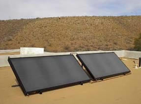
Standard flat plate solar collectors
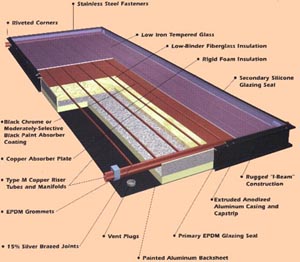
-
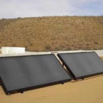
- Flat Plate Solar Hot Water Collectors
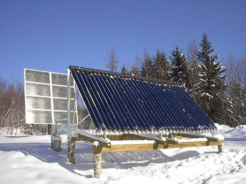
Evacuated tube solar collectors
-
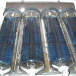
- Tubes
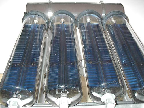
-

- Evacuated Tubes work great even in the winter
Zoning
We’ve seen that virtually any method of heating water will work for radiant floors and that PEX tubing is the best heat transfer medium. So, how do we spread that heated fluid to the living space?
Although it’s perfectly okay for even a large area to be a single zone, sometimes people want to break a space into multiple zones. A zone is any area controlled by a single thermostat and supplied by a single circulating pump. A zone can be tiny or huge. A zone can consist of many circuits or loops of tubing, or can be a single circuit. Circuit lengths should not exceed 400′ of tubing (300′ for 1/2″ PEX), but a zone may contain any number of circuits.
So, the question becomes: How many zones do I need? The answer depends upon your lifestyle, the size of your heated space, and the unique architectural characteristics of the building. As a rule, keep zoning to a minimum. There’s nothing wrong with treating an entire floor as one zone. By one floor, we mean one elevation. Remember, the first and second story of one home shouldn’t share a single zone. So, if you have a two story house, your system will be a minimum of two zones.
Minimum zoning is important because radiant heating is very even. You are warming not only the floor, but also every object in the room. As a result, the entire space tends to equilibrate. Treating every room in the house as a separate zone is not only a waste of time and money, but it won’t give you much control over a space that tends to seek the same even temperature.
Zoning entire sections of a floor makes more sense. The most common (and effective) procedure to zone your Radiant heating system, is through a method of discerning “Daytime” and “Night-time” areas. A block of rarely used bedrooms could be on their own zone, for example. Also, many people prefer to maintain their master suite at a cooler temperature than the rest of the living space. If there’s a lifestyle reason to maintain one section of a given floor at a noticeably warmer or cooler temperature, then zoning is appropriate.
Another example would be architecture features like sun rooms or great rooms with lots of glass. These rooms have a heat signature unlike the rest of the living space. During the day, a sun room can be 20-degrees warmer than the living room. If the thermostat controlling the zone is located in the living room, the sun room will receive heat it doesn’t need. The reverse is also true. At night, the sun room will give off much of its heat due to its large amount of glass. Trying to keep the sun room warm during a cold winter night would overheat the rest of the living area if both spaces shared the same zone. Of course, it goes without saying that window shades greatly reduce nighttime heat loss in high glass areas and should be installed whenever possible.
Adding a zone typically increases the cost from $600.00 to $800.00 depending on the application. These costs result with the addition of a manifold, Pump, Thermostat/Floor sensor, relay, fittings and valves, etc. These varied costs are dictated by the volume of each additional zone. The cost savings of additional zones are realized through comfort, control and energy savings due to the unnecessary overheating in a given area.
A garage would always be on its own zone. (return to top)
Multiple Circuits
So, if a zone can be any size, and each zone uses only one circulating pump, how far can the hot water travel before it looses all its heat?
The answer depends upon the size of the tubing used. The smaller 1/2″ PEX is limited to a 300 ft. run, the 7/8″ PEX to about 400 ft. So, if a zone is large enough to require more than, say, 400 ft. of PEX, the heated area must be broken up into multiple circuits, all approximately the same length. Similar lengths are important because you never want to give the water a path of least resistance to follow. If your zone consisted of three circuits, one 200 ft. long, and two 100 ft. long, the two shorter circuits would steal the water from the longer 200 ft. circuit because they would offer the pump less resistance. An inefficient heating system would result.
This is how it should be done. Let’s say that your entire first floor is one evenly heated space, one zone. You need 1200 ft. of 7/8″ PEX tubing, spaced 16″ on center, to cover the whole area. If you tried to run the hot water continuously through 1200 ft. of tubing, you’d end up with ice water by the time you got back to your heat source.
Instead, you can break up the zone into one of these configurations:
(6) 200 ft. circuits
(4) 300 ft. circuits
(3) 400 ft. circuits
You can see that none of the circuit lengths has exceeded 400 ft. In each case, the water is returning to the heat source before or at the 400 ft. point.
Keep in mind also that these circuit lengths are just examples. A circuit length should conform to each individual situation. The installer can be flexible within the above guidelines. If you are installing tubing in your floor joists, and you determine that the ideal circuit length for your situation would work out well as (5) 240 ft circuits… then by all means do it that way. (see The Floor Joist Installation for detailed installation instructions) (return to top)
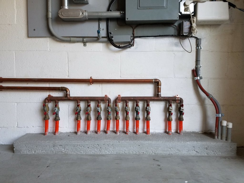
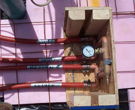
The Zone Manifold
A tank of efficiently heated water won’t do much heating unless it can be distributed effectively to the zones. For this we use a Zone Manifold. This is simply a factory built manifold containing all the gauges, valves, pump flanges, etc. necessary to mount multiple circulating pumps in one central location. It’s normally installed very near the heat source so that any pump, when activated by a signal from the zone, can draw hot water and send it to the floor.
If for some reason, the Zone Manifold must be located more than six feet (three feet for on-demand units) from the heat source, the pipe size between heat source and manifold should be increased in direct proportion to the distance. Contact one of our technicians for specifics and never use any piping material except copper to connect the heater to the Zone Manifold, i.e. never use PEX, PVC, ABS, black iron, or garden hose for this purpose.
A heating system’s supply and return pipe size is dictated by the total volume (all zones combined) in a system. We recommend copper tubing for both the supply and return from the heat source to the Zone manifold and back to the heat source, to minimize constriction of the (much needed) volume to the zone manifold. Constricting volume to and from the zone manifold may create “in fighting” from competing pumps as they may struggle for volume, denied via smaller (undersized) piping.
Every zone always has its own circulating pump. That way, the pump can be sized to match the amount of tubing in the zone. The fluid from the pump then enters the supply line to the zone, travels through the floor, then returns to the heat source. (return to top)
Supply and Return Lines
The Supply Line
In a floor joist installation, a supply header feeds the circuits within a zone. This header is simply a 3/4″ copper supply pipe that comes from the circulating pump. (See The Floor Joist Installation for detailed information on building the supply header.)
In a slab installation, the supply line is run to one side of a slab manifold (see photo below) that has already been installed as part of the slab pour. (See The Slab Installation for detailed information on installing the slab manifold.)
The Return Line
Every circuit of tubing will have a beginning (supply) and an end (return). After traveling the entire length of the circuit, the fluid flows into a return pipe, also 3/4″ copper. This return pipe leads back to the heat source where the water is re-heated and sent back to the supply side of the circuit. This cycle repeats until enough heat has entered the space to be warmed. Only when the thermostat in the zone has been satisfied will the zone pump shut off. (return to top)
Using Adaptors and Couplings
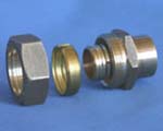
Adaptor
Adaptors
Normally, all supply and return lines are insulated with foam pipe insulation or fiberglass. This is to prevent heat loss as the water travels to and from the heated floor. Most of the time, supply and return lines are made of 3/4″ copper pipe. This is because you are already in copper pipe mode when you leave the circulator pump. Getting from copper pipe mode to plastic tubing mode requires a brass fitting called an adaptor.
Adaptors are very handy fittings. The ability to convert from copper to plastic, and back, at any time, gives the installer a great deal of flexibility when it comes to running supply and return lines. Even while threading the radiant tubing through floor joists, adaptors can be used to overcome obstacles in the joist bays, make super tight bends, etc.
Couplings
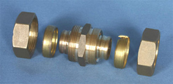
Coupling
Whenever the installer needs to connect plastic to plastic, use a coupling. Badly kinked, punctured, or crushed tubing can be easily repaired using couplings. Like adaptors, couplings are brass fittings.
See Connecting Adaptors and Couplings in the Installation Details section of this site. (return to top)
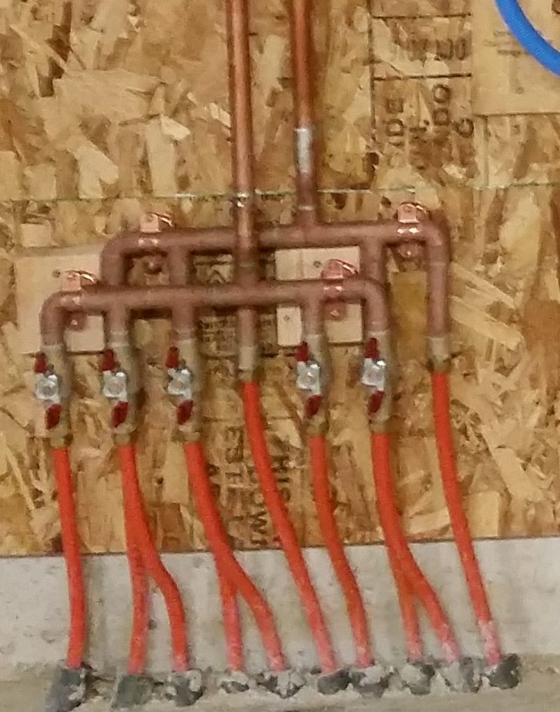
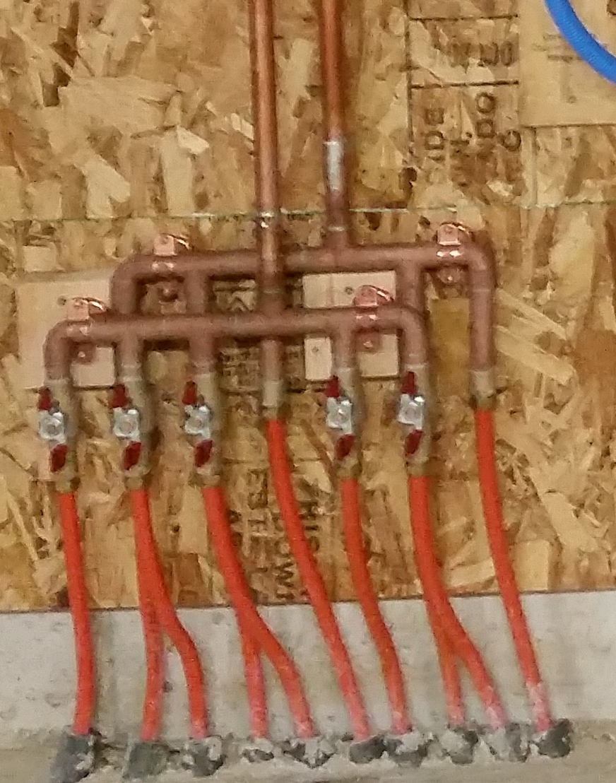
The Slab Manifold
Whenever radiant tubing is poured into a concrete slab, a slab manifold should be used. More than merely a method of splitting a supply feed into two or more branch circuits, the slab manifold also doubles as a pressure test kit. Built into every manifold you’ll find a pressure gauge and an air stem. Once the tubing has been installed and all the connections have been tightened with a wrench, use the air stem and an air compressor to pressurize the system to 50 psi. If several hours pass without any significant drop in pressure, you can rest assured that your tubing is ready for the pour.
-
- Example of “Wall mount” loop manifold

-
- Loop manifold with alternating supply & return
-
- Notice that the supply side of the manifold is joined to the return side by the pressure testing assembly.
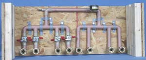
Slab manifold in box, ready for pour.
The manifold is also useful as a safety gauge during the pour itself. If at any time you question the integrity of the system, checking the pressure gauge will tell you instantly whether or not the tubing has been damaged.
The box used for shipping the slab manifold becomes the form to pour your concrete around. This prevents the concrete from coming into direct contact with the manifold and creates a “manifold well” in the slab to protect the tubing and connections from damage during later stages of construction. (Note: the photo shows the manifold box without the front panel installed.) (return to top)
We build our manifolds here in our factory. Each multiple Loop manifold includes ball valves for each pex circuit as this will also ensure better purging when filling the system. Equal pex lengths are the best way to ensure even balance and heating. The MOST accurate way to balance your system (with uneven lengths), is to measure the supply and return temperatures of each pex circuit. Shorter lengths will require more resistance so as to equalize flow when balancing with the longest length. The best way for properly equalized flow is equal circuit lengths.
We include (full-port) ball valves in our multiple circuit/loop, zone design. These valves are put in place for each pex circuit/loop in order to fill and purge separate lengths.
Some loop /circuit manifolds available today use Mechanical Flow meters, Balancing valves or Circuit setters. We don’t recommend them due to their stifling (flow sensing) design,… even at their “Wide Open” settings, resistance in these valves are apparent.
Mechanical Flow meters work by sensing flow via liquid movement and measures flow as the amount of fluid passing through the flow meter. This movement is metered through a resistance design, which inhibits flow and increases resistance/head pressure. Another disadvantage of mechanical type water flow meters for water measurement is that they may clog more easily when the liquid is dirty, contain particulates and create increased flow restriction etc. This can lead to increased maintenance issues. Mechanical water meters also do not work well when the water flow is low. The zone’s pump may not overcome this head pressure due to the resistance created by this resistance. There may (then) be a need to up-size the zone’s pump, OR the supply and return line’s size may be increased to lessen this (potential) issue. The pump size / model for each zone is dictated by the zone’s volume and supply and return piping,…This is based on using 3/4″ copper for zones with multiple circuits larger zones volume may require 1″ supply and return, again total zone volume will dictate this requirement. Each type of flow-meter has its own specific applications and installation constraints. There is no “one size fits all” flow-meter.
Our findings support the a-fore stated information and is based on years of shop and field experience as well as customer feed back through diagnosed troubleshooting.
Mounting the Mechanical Components
Zone Manifold
Zone Manifold
The zone manifold is divided into two sections…supply side and return side. Both sections should be mounted fairly close to the heat source. In multiple zone systems containing many pumps, the supply side of the manifold can be quite heavy so care should be taken to mount it securely. When you receive your manifold, you’ll notice that we’ve included a piece of plywood. The plywood should be removed and mounted on the wall next to your heat source. This will provide a secure foundation for both sides of your manifold and give you a board already precut to the width of your particular manifold.
Also note the “test caps” soldered onto the ends of the zone manifolds & the Expansion and Purge Kit. We install these for pressure testing purposes and to prevent debris from entering the manifold during shipping. These caps should be removed before plumbing the manifold.
In the bag of mounting hardware included with your order you will find two excellent mounting assemblies: 1) 1 1/4″ bell connectors, and 2) split ring hangers, complete with precut all-thread rods and the cast iron plate that the all-thread screws into.
The bell connectors are mounted to the plywood and attach to the main body of the manifold.
The split ring hangers are also mounted to the plywood, of course, but they attach to the 3/4″ copper pipe just below the circulating pump. The piece of all-thread is used to bridge the gap between the plywood and the split ring hanger and provide a strong support.
You’ll also notice identical brass tee fittings on each end of the zone manifold.
The outlet of the tee is threaded. Depending on how you decide to orient the manifold in relation to your heat source, this threaded outlet will contain either a drain valve or an in-line thermometer.
Obviously, you’ll want to install one of the in-line thermometers at a point where the hot water first enters the supply side of the manifold. This way you can monitor the fluid temperature on its way to the floor. The second in-line thermometer is installed so that you can monitor the temperature of the water as it leaves the return side of the manifold and travels back to the heat source.
Install the two drain valves in the tees opposite your in-line thermometers. These valves are provided as a means of draining the radiant system should that ever become necessary.
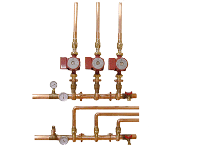
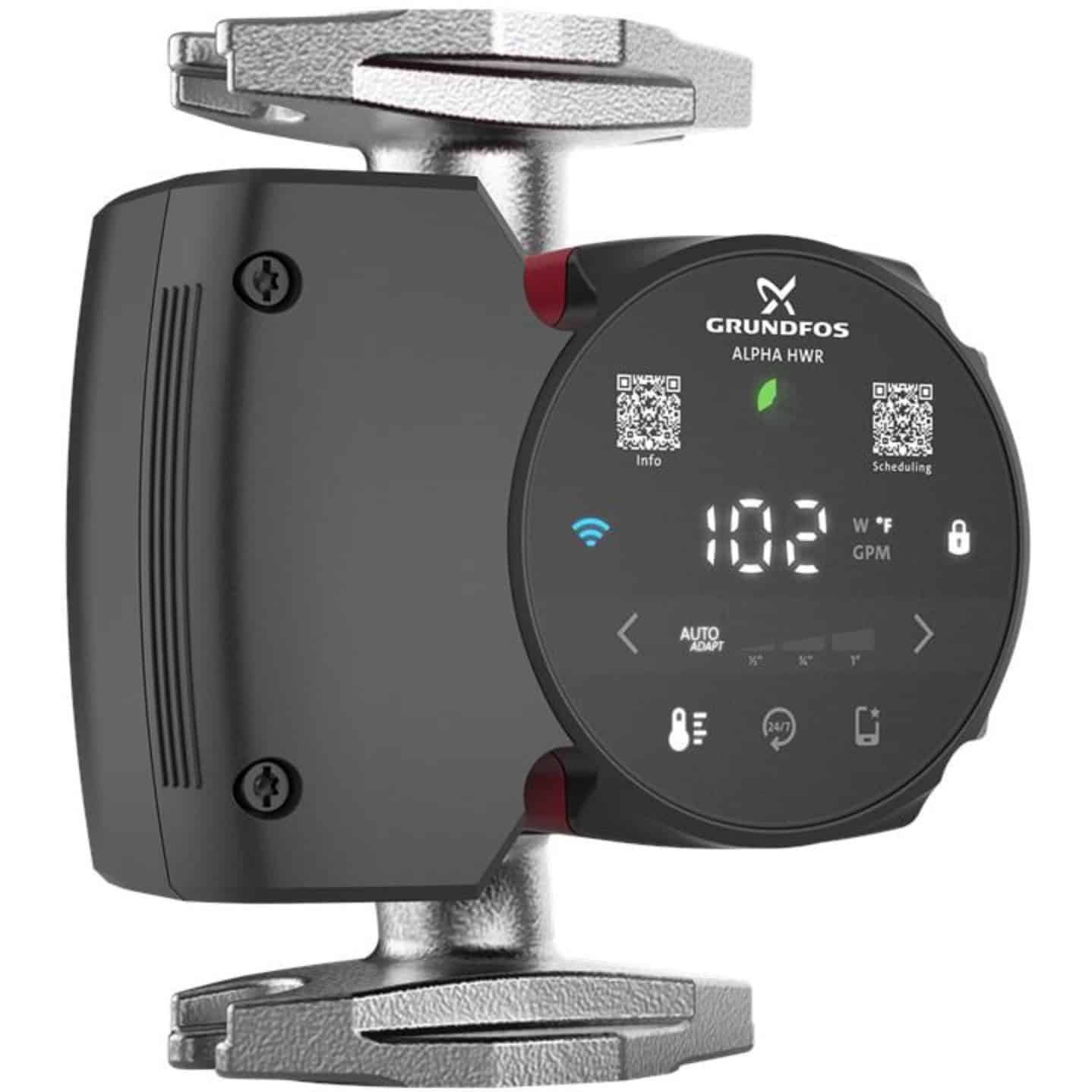
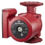
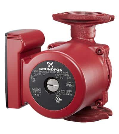
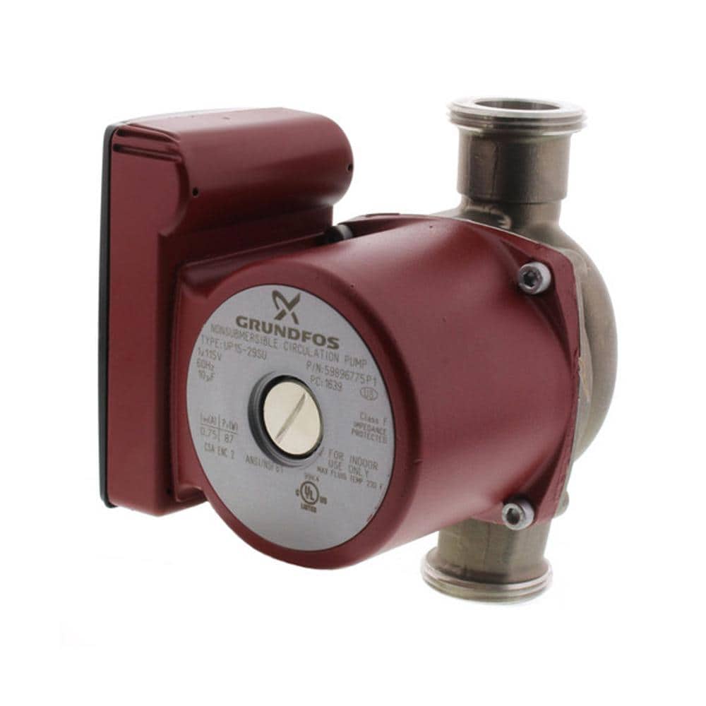
Circulating Pumps
-
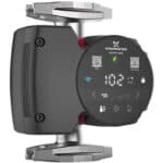
- Grundfos Alpha pump boasts 50-75% efficiency
-
- A conventional, high-quality radiant circulating pump manufactured by Grundfos
-
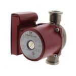
- Grundfos stainless/potable union style pump
Once the zone manifold is mounted, the circulating pumps are very easy to install. The pump flanges are built into the manifold so attaching the pump is simply a matter of aligning the pump with the flange and bolting it in.
For single zone systems (i.e. one pump) always orient the circulating pump so that the arrow on the body of the pump is pointing upward. This way any air rising in the system is pushed up and away from the pump. Note: Radiant Floor Company has designed what we call “Radiant Ready” system. These are pre-plumbed and pre-wired single-zone plumbing assemblies mounted on a plywood board. Depending upon which package is needed, i.e. for an “open” or a “closed” system, only four or five solder connections are needed to complete the mechanical part of the radiant system.
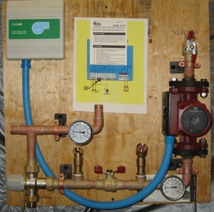
Radiant Ready “J”, a single zone system for use with an existing boiler.
For multiple zone systems, you’ll want to pre-wire the pumps with 14 gauge wire before you install them into the Zone Manifold. Follow your local codes for specific wiring guidance. Some codes require flexible conduit from the relay box to the pumps, others allow a simple Romex connection.
Pump Controller

Pump Controller Box
The pump controller box is usually mounted fairly close to the rest of the mechanical components. However, some people choose to locate it some distance away. The controller displays a green light to indicate power to the system and red lights to indicate which zone or zones are currently operating. It can be a very handy way of monitoring your system and you may want to install it in some location that you frequent often. Radiant systems are silent. If you’re like me and are curious about the rhythms of your system, you’ll want your controller somewhere that you can conveniently see it.
Wiring the controller box is generally very simple and schematics are included with every system. But, if you have questions, just contact one of our technicians and they’ll happily walk you through the process.
Expansion and Purge Kit
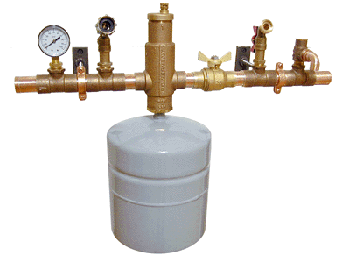
For Closed and Heat Exchanger systems, you’ll need the Expansion and Purge Kit (EPK). This consists of an expansion tank, an air eliminator, fill and drain valves, a pressure gauge and a pressure relieve valve. The EPK is pretty much factory assembled. You’ll have to screw the expansion tank into the bottom of the air eliminator because the tank is shipped in a separate box, but that is a simple operation.
The EPK makes it very easy to fill and simultaneously purge air from your newly installed tubing, and the expansion tank component acts as a sort of “shock absorber” in a closed system. When water heats up, it expands. The flexible membrane in the tank absorbs that expansion.
In addition, the pressure gauge in the EPK helps you charge the system with the proper 15-20 PSI, and during the life of the system, lets you know when more fluid needs to be added by indicating a pressure drop below 10 PSI.
The pressure relief valve is a safety device very much like the pressure and temperature relief valve on your water heater. It protects the tubing from excessive pressure.
Mounting the EPK is similar to mounting the zone manifold. Use split ring connectors and all-thread to secure the EPK to a wall next to your heat source. In Closed and Heat Exchanger systems the EPK is installed between the heat source and the zone manifold, so that the plumbing itself offers a great deal of support to the assembly. Always install the expansion tank after the EPK has been mounted. (return to top)
A world of Possibilities
One of our customers, CAD Master Dan Willis of Grants Pass, Oregon sent us this schematic of a system we designed for him utilizing solar and wood, with propane for back-up.
It illustrates a basic fact: Whether you’re heating a single small zone with a standard, tank-type water heater, or, as in Dan’s case, blending multiple heat sources into a harmonious, multi-layered system, Radiant Floor Company can help.
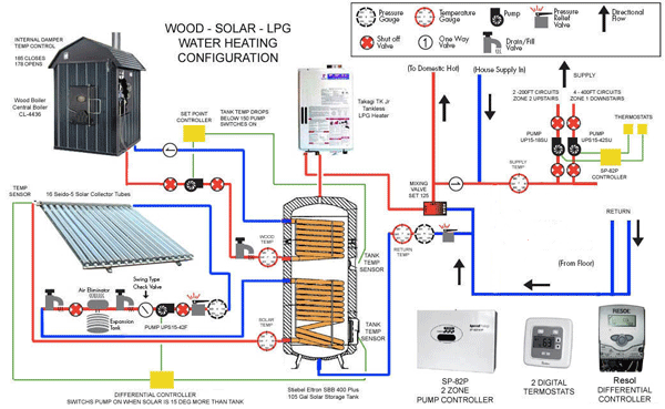
Solar Wood Hybrid Radiant Heat System Schematic