Standard Wiring Diagrams for I-Link Controllers
Table of Contents
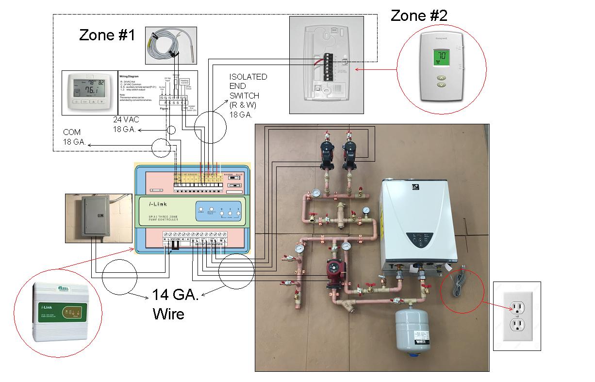
Important note: Aside from the Electro boiler unit, there is no direct electrical connection between any I-Link Relay and any model of on demand water heater. The only electrical connection to the On Demand / Tankless water heater,… is the power (plug) to/from the unit (regardless of the number of zones). The water heater is triggered when the unit senses a minimum of 1/2 gallon per minute of flow. The water heater activates when any or all zones call for heat and the pump(s) circulate liquid through the unit, thus creating the “flow” that signals the water heater to fire up!
A quick start wiring guide for multi-zone systems. For greater details scroll down the page for more schematics.
We offer unlimited technical support ~ toll free 866-warm toes (927-6863)
Basic single zone controller
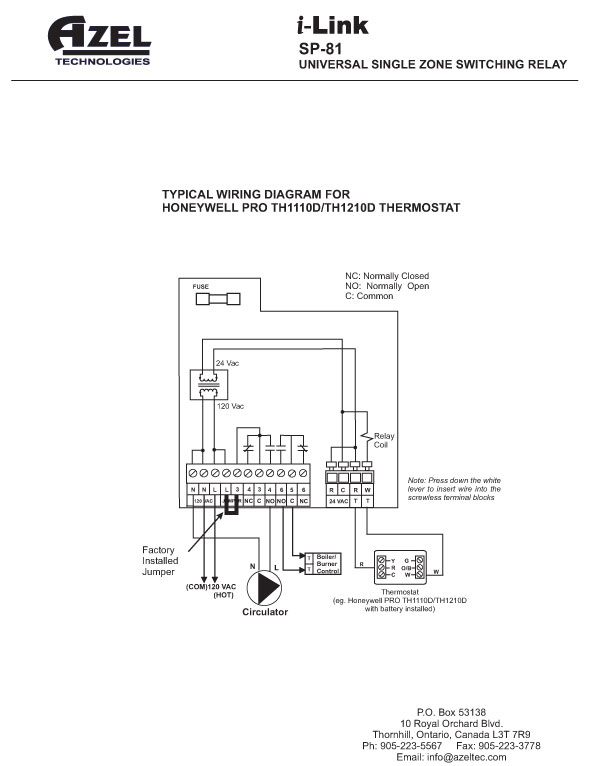
So…..If you have a simple, single zone radiant system and are using the I-Link SP-81 relay that we provided with your system, follow the schematic below.
Single zone controller activates a pump when thermostat calls for heat.
18/2 thermostat wire from the thermostat in the zone connects to terminals R/W. Red or White can go to either terminal. Pushing back the tab above the terminal block allows easy insertion of the wire. 14/2 Romex electrical wire is recommended to power the Radiant heating system (relay / pump).
NOTE: “Power to Thermostat” on the above schematic indicates 24 volts AC coming from the controller to energize a digital display on thermostats that do not use batteries for this purpose. The thermostats we sell use batteries, so this feature is not required for the digital display on our thermostats. But, above all, do not connect a 120 vac line to these terminals.
(return to top)
Basic “multiple zone” controller
Multiple zone systems are generally controlled by a single box containing multiple relays. Like the SP-81 above, the multiple zone controllers use the same basic terminal block configuration for the low voltage (thermostat) and the line voltage (running the circulator pumps). A row of orange tabs along the top of the controller panel allow you to insert the thermostat wires and a block of terminal screws along the bottom labeled N (neutral) and L (load) make wiring each zone pump very easy.
Of course, in all applications, the relay box must be energized by a 110 volt line (see schematic below) from your circuit panel. Either that, or a branch from an existing circuit can be run to the controller box. It’s also a good idea to wire a standard light switch into the controller circuit so that the entire radiant system can be turned off at one central location. If your relay box is wired through a switch, you won’t have to rely on the thermostats alone to shut your system off during the cooling season. This feature could prevent someone from “toying” with your thermostats and sending heat to your floor in the summer.
In this example, the thermostat connections are made at the upper row of “T”, terminals T1, T2, T3, etc. The circulator pumps are wired to the lower, high voltage terminals for zones 1, 2, 3, etc. on the 120 volt block. The lines from the power source (circuit panel) are connected to N (common) and L (hot). The factory installed jumper is not moved.
Below is another example of a multi-zone controller, (i-Link SP-83), but for a very straightforward system. In other words, the controller is nothing more than three radiant floor zones, activated by three thermostats. There is no need to use the “system pump” terminals, no need to use the “XX” terminals to activate a boiler, and no “priority zone” for an indirect water heater.
The basic wiring is essentially the same for all multiple zone controllers. A multi-zone controller may contain from two to six relays, but the wiring procedure stays consistent. Of course, the i-Link controller can also be wired for special applications and the most common ones are illustrated below.
(return to top)
Special Wiring Diagrams for the i-Link Controllers
Certain situations require the i-Link controller to do more than simply activate a circulator pump every time a zone calls for heat. The following schematics illustrate three common specialty applications.
Activate a boiler with a single zone controller
Single Zone Controller activates a boiler every time a zone calls for heat
The “5” and “6NO” (normally open) terminals merely close a circuit every time the radiant zone thermostat calls for heat. These terminals do not send any voltage to the boiler. The boiler itself contains a transformer that is activated whenever this circuit is closed.
(return to top)
Use the above “multi-zone” schematic if you have more than one zone and you need to use the “end switch” (XX connections) on the i-Link Controller to activate a boiler whenever any of the radiant zones call for heat.
Activate a gas valve from a zone controller
Controller activates gas-fired boiler whenever a zone calls for heat
The controller can interface with the existing boiler transformer and activate the gas valve by using the above schematic.
(return to top)
Wiring the Heat Exchanger/Primary Loop System
Activating a “system pump” whenever any zone calls for heat
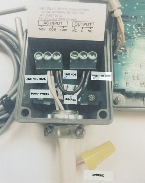
This is the schematic to use with a Heat Exchanger or Primary Loop system. The pump running the heat exchanger/primary loop is called the system pump. Obviously, it needs to run when any zone calls for heat.
For (either) Primary loop pump or Heat exchanger pump connections, both neutral (white wire) and load (black wire) to the “System pump” connections at the bottom of the relay box (these connections are to the left of the zone pump connections. All ground wires will wire nut together inside the relay box. The ground wires will ground at/from the power source, flow through the relay box (via wire nut) and terminate at each pump.
The factory installed jumper is left in place.
(return to top)
Wiring the Thermostat
Honeywell Pro 1000 Thermostat (6 terminal)
The Pro Th1000 is a versatile, multi-functional thermostat, and very easy to use and wire. But you’d never know it by looking at Honeywell’s INSTALLATION MANUAL. Therefore, we recommend that you use this page and the accompanying photo to make the process quick and simple.
STEP 1:18 gauge thermostat wire is recommended. Three (3) wires (R-W & C) may be used if you choose to utilize the 24 volt power feature from the relay and eliminate the need for batteries for the Honeywell thermostat. These wires connect to both of the relay and thermostat (R-W & C) terminal connections. Remove the front cover and connect one of your 18/2 gauge thermostat wires to the “R” terminal, and the second wire to the “W” terminal. The wires are totally interchangeable. But for the sake of simplicity, put the “red” thermostat wire in the “R” terminal and the “white” thermostat wire in the “W” terminal.
STEP 2: Install the (2) AAA batteries and re-install the cover. This step not needed with 3 wire connections (See Above)
STEP 3: Deactivate the “Five minute delay” function. (This function protects air conditioning compressors from over-cycling and is useless for radiant heating purposes).
A) Deactivate the “delay” by pressing BOTH toggle buttons (^ and v) and holding them for three seconds. This takes you into “program” mode.
B) Once in “program” mode, press both buttons simultaneously and toggle up through the numbers to program mode #5.
C) The factory setting is “1” (5 minute delay “on”) and you’ll want to set this mode to “0” to deactivate the 5 minute delay feature.
D) Press the “down” toggle (“v”) button and “0” will display on the screen.
E) Press both toggle buttons one more time to get out of “program” mode. The current “set-point” temperature will be displayed.
STEP 4: Use the toggle buttons to set the thermostat to any desired temperature.
Wire positions for Honeywell Pro 1000 (6 terminal model)
Wiring and Set-up for the Honeywell Pro 1000 Thermostat (8 terminal)
The “8 terminal” version of the Pro 1000 is also simple to wire and program, but configured slightly differently. Instead of (2) 3-terminal blocks, left and right, this version has (1) vertical 8-terminal block in the middle. It looks like this:
The set-up procedure goes like this:
STEP 1: Remove the front cover and connect one of your 18/2 gauge thermostat wires to the “R” terminal, and the second wire to the “W” terminal. The wires are totally interchangeable. But for the sake of simplicity, put the “red” thermostat wire in the “R” terminal and the “white” thermostat wire in the “W” terminal.
STEP 2: Install the (2) AAA batteries and re-install the cover.
STEP 3: Press BOTH toggle buttons (^ and v) for two seconds. This takes you immediately to “Function #5”. Toggle with the down arrow to set “Function #5” at 3.
STEP 4: Deactivate the “Five minute delay” function. (This function protects air conditioning compressors from over-cycling and is useless for radiant heating purposes).
A) Pressing BOTH toggle buttons (^ and v) jumps you through the various functions. Toggle by pressing both buttons until you reach function #15. Use the down arrow to set this function to 0 (zero).
Note: You won’t have to toggle fourteen times to get to function #15. In fact, you’ll only have to toggle three times. That’s because thermostat designers don’t count in sequence like the rest of us. They’re engineers, and in their unknowable quantum world numbers represent esoteric design concepts instead of an orderly system of arrangement. To us, removing a banana from a bunch of six, leaves five bananas. To a Honeywell engineer, five remaining bananas represent “function #13”. Adding a banana to the bunch would be expressed as “function #23”, or in layman’s terms, 6 bananas.
Robert Shaw brand thermostat
If you have the Robert Shaw brand thermostat, use the following schematic.
Robert Shaw circuit diagram
Controlling a pump with a “floor sensor”
The AZEL D-508F thermostat/floor sensor (shown below), can use either ambient air or floor temperature to control a zone. Use this link for more information and installation instructions: https://azeltec.com/images/D-508Finstruction.pdf 

Four (4) wires (18 gauge) are needed for the Azel (D-508) Floor sensor/thermostat. “R&C” (24 volt power) terminals at the relay connect to “R&C” terminal connections on the D-508 thermostat. The “R&W/TT” thermostat terminal connections at the relay, wire to terminals # “1&2” on the D-508 thermostat. It is important to note that stranded wire is recommended when extending the (22 gauge) sensor wires that originate from “SS” terminals at the thermostat, these (extended) wire connections should be SOLDERED and insulated (taped etc.) from each other, to insure absolute continuity as this is an “OHM” resistant sensor.
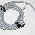
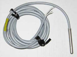
The Shut-off sensor/relay uses a small sensor to activate a circulator pump. The sensor itself is a small thermistor normally fed into a short tube of PEX that has been cast into a radiant slab. Of course, the sensor can also be installed in a joist cavity to monitor the floor temperature in a staple-up system. This sensor monitors the temperature of the actual floor and ignores the room’s air temperature. It is very useful in radiant zones that have more than one heat source.
If a forced air system or a wood stove is used regularly in a radiant zone, for example, the standard air monitoring thermostat normally used to control the floor would be off most of the time. Instead, the embedded sensor allows the occupants to maintain a baseline floor temperature.
Johnson Controls “Set-Point controller” Shut-off and Temperature Thermistor:
-
- Johnson box
-
- Floor Sensor
-
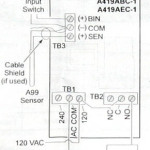
- Wiring schematic
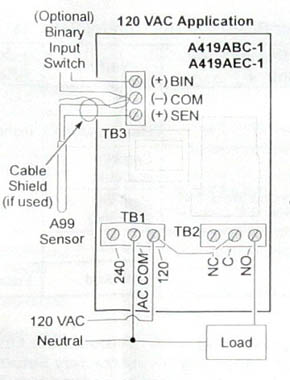
The properly wired floor sensor
The Shut-off sensor/relay is also available in a low voltage (24vac) model. In this application, the floor sensor doesn’t directly power the radiant circulator pump. Instead, it functions very much like a standard, low voltage wall thermostat — it connects to a relay, which in turn powers the circulator. Applications using the low voltage shut-off sensor/relay are wired as in the photos below.
-
- Mock-up showing low voltage “floor sensor” as wired to an I-Link relay
-
- Close-up wire connections
Other applications for the sensor are as varied as your imagination. It can be used to monitor the water temperature in a storage/back-up tank, for example. The sensor is attached to one of the pipes entering or leaving the storage tank, insulated with foam or fiberglass, then an 18 gauge thermostat line is run from the sensor to the relay.
When the tank temperature drops to whatever set point you decide, a circulator pump turns on and draws heat from a heat exchanger. This setup would be useful for a system using an outdoor wood boiler connected to a continually active heat exchanger. Based on whatever parameters you set, the storage tank draws the heat it needs from the heat exchanger to maintain a constant tank temperature.
Any thermal storage medium can be heated in this manner, including hot tubs, greenhouse growing beds, aquariums, worm farms, towel warmers….you name it.
This controller can also be used in reverse. In other words, the relay can be activated when the temperature in a tank of water rises to a given set point and the tank needs to be cooled down.
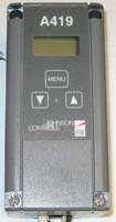
The most common use for this approach is the “Heat Dump Package”, a plumbing arrangement we use to divert excess heat from a solar loop. The jumpers inside the A419 are configured to COOLING MODE (both jumpers – jump 1 and jump 2 – are positioned in the “removed” position on their pins) and the sensor is attached to the HOT outlet pipe of the solar storage tank. When a high set point in the storage tank is reached, the heat dump circulator activates.
Spring Timer for snow melt systems

The Solar Differential Controller
Resol DeltaSol BS
The Resol DeltaSol BSSolar thermal systems generally use a special relay called a Differential Controller. As the name implies, this relay activates a pump or pumps when a span (or difference) between two temperatures is achieved. In other words, when the temperature at the solar collector is X degrees hotter than the temperature at the bottom of the solar storage tank, the differential controller activates the necessary pump(s) and draws that useful heat into the system.
Transferring heat from a hotter to a cooler tank in order to equalize the temperature in both tanks and increase total storage capacity is another common use for a differential controller.
Two sensors (tank and solar) are required for a proper “differential”. The tank sensor is attached to a pipe near the bottom of the solar storage tank, or into a designated “well” in some tanks.
The second sensor reads the water temperature as it leaves the solar collectors. Both sensors must be insulated (with fiberglass or foam) to prevent ambient temperature from influencing the reading. It should be noted that a sensor clamped to a hot pipe will NOT accurately read the actual water temperature. In fact, the water will generally be 15 to 20 degrees warmer than the sensor indicates.
Fortunately, for the purposes of a well functioning solar hot water system, actual water temperature is not important (unless, of course, it’s too tepid for a hot shower). What matters is the difference between the water temperatures at the two locations. After all, if the water is actually hotter than what the sensor indicates, so much the better.
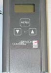
STANDARD DISPLAY MODE
The Resol controller is activated by three buttons: FORWARD (far right), BACKWARDS (far left), and the SET button (center).
When in STANDARD DISPLAY MODE, that is, not in PROGRAM MODE, the user can toggle between the three primary fields:
1. COL (collector sensor)
2. TST (tank sensor temperature)
3. HP (hours of solar gain accumulated)
PROGRAMMING
Press and hold the FORWARD button (right button) for TWO seconds. This puts the RESOL into PROGRAMMING MODE, starting with DT-O (Delta T, ON).
Note: Holding the FORWARD button down will begin a rapid toggle through all the programming options, so if you skip past DT-O, just use the BACKWARD button to step back.
The Delta T is the difference between the temperature at your solar collectors and the temperature at the bottom of your storage tank. When the Delta T is reached, the Resol controller activates the solar pump and circulates heated fluid from the solar collectors.
See CHOOSING A DELTA T (below) for advice on the best Delta T for your situation.
To set your Delta T ON temperature, enter PROGRAM MODE, and press the center SET button. The SET icon will start flashing on the screen. Toggle up or down to your desired temperature differential. Press SET again to lock in the program.
The same procedure is used for the next screen, DT-F, the pump OFF parameter.
This field lets you decide when to shut your pump off. By the way, this temperature must be at least 2-degrees cooler than the pump ON
temperature.
As a rule, when the fluid in your solar loop is only a few degrees hotter than your tank temperature, there’s little to gain by circulating the fluid. Shut the pump off and allow the collectors to heat up again. A 3 to 5-degree temperature differential is probably fine for this field.
S MX, the next field, allows you to set the MAXIMUM TANK TEMPERATURE. The factory default setting is 140-degrees. That’s way too low. Set this field to at least 180-degrees. You may even want to go higher. The Resol controller allows you to heat your tank to 205-degrees. That’s only 7 degrees away from steam, but with a properly installed tempering valve (a must for any solar system) to protect your household from scalding, you may as well store as much heat as you can.
However, if you want a lower maximum temperature, simply press the center SET button and toggle down to the desired temperature. Press SET again to lock in your preferred temperature.
The next field is EM. This means EMergency shutdown. If for some reason there are delicate, heat sensitive components in your solar loop, this setting will shut down your pump at the temperature you determine and prevent overheating. The factory setting is fairly low at 285 degrees because nothing in our system is even close to the danger zone at that temperature (the circulator pump, for example is rated to 400 degrees), so leaving it at the factory default temperature should be fine.
NOTE: The RESOL is a very advanced controller and offers many features that most people won’t need. The rest of the fields fit into this category and are useful for specialty applications. For a normal, basic, solar water heating system, ignore these fields. The factory default for these settings is OFF.
However, having said that, a thorough reading of the RESOL manual might inspire some users to experiment with these more advanced functions.
Quick Reference Guide
Only the Collector Temperature (COL), Tank Temperature (TST), and Accumulated Solar Gain (HP) fields are available in Primary Mode.
Hold the FORWARD button for two seconds to enter Program Mode.
Toggle to desired field, press SET, use FORWARD or BACKWARD to find desired value, then hit SET again to confirm.
Note: After approximately 45 seconds of idleness, the display light goes off. Press the FORWARD button to re-light the display, press again to toggle to desired field.
Also, after a few MINUTES of idleness, the RESOL controller will automatically leave PROGRAM MODE and return to PRIMARY MODE.
If you want to leave PROGRAM MODE before the automatic return, simply use the BACKWARD button and toggle back to COL (field number one).
Choosing a delta T
Why a Wide Differential is Generally Best
The “collector loop” is the total length of 3/4″ copper pipe, both supply and return, that connects the solar array to the mechanical components, i.e. heat exchanger, storage tank, etc. This loop can be quite short (collectors located on the roof of a garage with mechanical equipment only fifteen feet below), or quite long (collectors grounded-mounted sixty feet from the house). The pipe in the short loop totals thirty feet (.8 gallons of fluid) . The long loop, one hundred and twenty (3.2 gallons of fluid).
In both these cases, the fluid in the collector loop must be brought up to temperature before the system will “stay on” for any length of time. The reason is because, early in the morning when the sun starts warming the collectors, most of the fluid in the collector loop is still cold. However, once the sun hits the panels, the fluid at the top of the collector, nearest to the collector sensor, warms up quickly and triggers the system. But, as soon as the colder fluid in the loop circulates passed the sensor, it cools down again.
This fosters a completely normal condition known as “short cycle”. Expect the solar pump to short cycle until the water in the overall collector loop heats up. If the collector loop is long, and the sun is weak, many gallons of chilly fluid must warm up before any useable heat can be transferred to the storage tank. This may take time.
Rule of thumb: Keep the collector loop short…and insulate it well.
You can see from the above description that a “tight” differential (8 to 15 degrees) increases the short cycle effect. Especially if the collector loop is long and the array is small (i.e. limited heating capacity). The widest possible differential in this situation would minimize the system’s tendency to shut off and on every few seconds.
However, if your system is high capacity (many flat plate collectors or more than 48 evacuated tubes), and your collector loop is short, a tighter differential activates the system earlier and more usable heat is gained.
Large heating capacity and short collector loop = tight differential (8 to 15 degrees)
Small heating capacity and long collector loop = wide differential (20 to 24 degrees)