Installing floor joists
Table of Contents
- Installing floor joists
- Running Multiple Loops of Tubing Within a Zone
- Threading the Tubing Through the Joists
- Skip Joist Method For Tubing Installation
- Building Headers
- The Three Main Header Types
- The Aluminum Heat Diffusion Plates
- Installing the Radiant Barrier
- When Running Double the Normal Amount of Tubing Makes Sense
- Installing Radiant Tubing in Structural Trusses
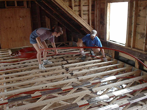
A floor joist installation presents some unique challenges not found in the wide-open, more flexible environment of the slab on grade installation. However, with a few guidelines, these challenges can be easily overcome. Check out our video Radiant Floor Heat Tubing Installation in Floor Joists, and read this page for a full description.
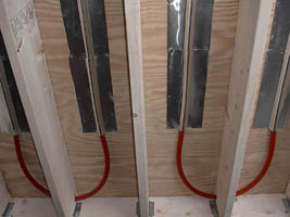
Typical floor joist installation using 7/8 ” PEX tubing, 16″ on center
First, it’s important to remember that, normally, Radiant Floor Company assumes that all heat exchanger tubing, whether 1/2″ PEX or 7/8″ PEX, is fed by 3/4″ copper supply and return lines. Because we never know how far away the heat source is from a given zone, we spec the proper amount of tubing to fill the zone only. In other words, the plastic tubing is in the heated floor and does not necessarily go back and forth to the water heater or boiler.
Having said that, keep in mind that the plastic PEX tubing can be used for your supply and return lines if: 1) you order extra tubing, and, 2) in your situation it makes sense to take advantage of the flexibility of PEX.
We do however recommend a minimum of 3/4″ copper tubing for supply and return lines when feeding a zone with multiple circuits of pex to and from the zone manifold. The reason for this is, volume and (potential) head pressure that is created when these supply and return lines are stymied. For example, 3/4″ pex (by itself) is (for the most part) fine (depending on the zone’s volume) BUT the inside dimension of a 3/4″ pex adaptor is nearly 5/8″, (much smaller) and therefore creates resistance / head pressure. The zone’s pump may not overcome this head pressure due to the resistance created by the adaptor’s decreased volume output. There may (then) be a need to up-size the zone’s pump, OR the supply and return line’s size should be increased to 3/4″ copper as this will lessen this (potential) issue. Feel free to contact a Technician with any questions.

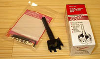
In some situations, using PEX tubing for the supply and return lines makes sense. The fitting shown above (left) allows the installer to run multiple radiant circuits without using a rigid copper supply header. The photo on the right shows the “self-feed” bit recommended for drilling the 1 1/2″ hole through the joists.
An example of this might be an installation in a geodesic dome or other unconventionally shaped structure. The plastic tubing would easily conform to the radius of the structure, follow the curve as it were, and could greatly simplify getting the supply and return lines from point A to point B. Other examples would be tight, difficult to access crawl spaces, cluttered, cramped joist cavities, or any area where running rigid copper tubing would be very difficult. Many people use a “hybrid” method. This is a combination of copper and plastic supply and return lines. Our brass adaptors allow you to convert from copper to plastic, and back, as often as necessary.
For example, you may start your supply line from the circulator pump with 3/4″ copper, run twenty feet quite easily, then encounter an obstacle you’d prefer to snake around. Using a brass adaptor, you convert to plastic, squirrel your way up, down, around, and through….reach the zone, then convert back to copper. Since the brass adaptors are meant to solder into any 3/4″ copper fitting, it’s always easier to be in copper mode when actually at the zone. This is because most zones require multiple even loops of tubing.
Running Multiple Loops of Tubing Within a Zone
Unless a zone requires 400 feet or less of tubing (300 feet for 1/2″ PEX), the zone must be broken up into even multiple loops. By even, we mean loops that are within, approximately, 10% of each other in length. By keeping the loops roughly equal you don’t give the water a shorter “path of least resistance” to follow and the heat in your entire zone will be balanced.
Most installations require multiple loops of tubing within one zone. If a zone is very large and requires, say, 1600 feet of tubing to adequately cover the entire floor, then that floor would be broken up into (8) roughly 200 foot loops all fed by a common 3/4″ copper supply line. The copper line acts as a header, filling with water first, then simultaneously feeding all the loops. The water then travels only 200 feet before entering a similar 3/4″ copper “return” header and making it’s way back to the heat source. This is why it’s easiest to use copper for supply and return lines.
Note: As mentioned above, PEX can also be used for headers. But expect to pay a lot more for fittings (PEX tees are expensive) and it goes without saying that soldered connections are preferred whenever possible.
The brass adaptors will solder into a 3/4″ copper tee at the beginning of every PEX loop. Basically, you build a manifold as you go. Your copper header arrives at the zone, adapts to PEX at the beginning of the first loop, snakes up and down “X” number of joist bays, then terminates using another adaptor into the copper return header. The supply header is then carried from the first copper tee to the beginning of loop number two, another tee is installed, another adaptor is used, and the process is repeated. On the final loop, a 3/4″ 90 degree elbow is used instead of a tee.
And, to take the above example a step further, keep in mind that it would be acceptable to install the same 1600 feet of tubing as (4) 400-foot loops. That’s because with 7/8″ tubing, the hot water can travel 400 feet before it starts getting too cool to do you any good. However, it’s generally preferable to run several shorter loops, than fewer longer ones.
If your installation requires multiple circuits of tubing within a single zone, a ball valve should be installed on the supply side of each circuit. These valves will come in handy when you fill the system and purge air out of the newly installed tubing. Especially in a large zone, the air in the tubing can offer quite a bit of resistance and it’s easier to purge the zone one circuit at a time. In addition, if the logistics of your situation requires that your multiple circuits are of uneven length, that is, not within 10% of each other in length, then the ball valves can be used to “balance” the flow between circuits. That’s not the best way to balance a zone, but it’s sometimes necessary.
The exact length of the loops, within the above guidelines, is determined by the situation. Radiant Floor Company generally provides 200 foot rolls of tubing for floor joist applications. This is because manhandling a roll larger than 200 feet can become a hassle. But upon measuring the length of your particular joist bays, you may determine that the perfect loop length for your installation will be, say, 270 feet. If this is the case, it’s perfectly acceptable to add 70 feet to each 200-foot roll. In floor joist applications, use as many couplings as you need….not only to add to a roll, but to make the job of running the tubing easier.
Threading the Tubing Through the Joists
The first thing to recognize about this phase of the installation is that it’s not a one-person job. Many people have called us claiming to have installed the tubing by themselves and we’ve never questioned their honesty… just their sanity. Running multiple 200-foot loops of 7/8″ tubing doesn’t have to be a nightmare, so why make it into one? As in most phases of construction, this project should be a two-person job.
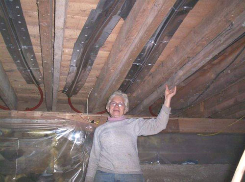
The “Queen of Joists”
Well, as if to prove the exception to every rule, Charlene Wood, age 67, of Newport, Vermont installed 7/8″ Pex in these floor joists — by herself — and then proceeded to install the heat diffusion plates. Of course, we still recommend that any Pex installation be a two person operation, but Charlene exemplifies the extraordinary talent and determination of our many do-it-yourself customers.
Start by drilling your joists in the easiest possible way. A 1/2″ right angle drill is the best way to go and so is a self-feed drill bit. Milwaukee makes an excellent one. Use their 1 1/2″ size.
Drill the hole an inch or two below the bottom of the sub-floor…..whatever allows you to drill the holes comfortably. Remember, you’ll probably be drilling a lot of them. Now, determine which “pattern” of tubing run you wish to use. Running up and down each joist bay works fine with 16″ on center joists. But if your joists are 12″ on center, you may want to try the “skip a joist” method illustrated below and in our installation manual. This method gives the tubing the widest possible bend and, as an additional bonus, both supply and return lines will end up on the same side of the room.
Skip Joist Method For Tubing Installation
Skip joist method schematic
This method allows for smooth, wide turns by skipping every other joist, then returning through the missed sections in one continuous loop, thus eliminating the need for a separate run.
If your joists are 24″ on center, run one length of tubing per joist bay, then double back and repeat the process. You’ll end up installing a very high performance floor, with two lengths of tubing per bay, approximately 12″ on center.
Whichever method is chosen, the best results will be obtained if the tubing is used at room temperature or above. Like with all plastics, the colder the tubing, the less flexible it will be. However, with two people working at roughly opposite ends of the room, the tubing is flexible enough to be snaked through the joists a few feet at a time, slowly, one worker feeding, and one taking up slack.
The tubing can lie flat on the floor between the two installers. It helps to counter-spin the roll to loosen it up and help the tubing unfurl off the roll easily. Always take your tubing from the outside of the roll, never the inside.
Then, as you’re slowly feeding the tubing through the joists, allow it to “gather” below the joist bay ahead of you. 15 or 20 feet of tubing can begin coiling toward the floor as you push it ahead of you. But don’t “gather” too much. Give yourself just enough to get through the hole in the next joist, then feed some more, gather some more, and gradually work your way through the bays. Feed, take up slack, feed, take up slack….slowly and steadily. In this manner, two or three people can run hundreds of feet of tubing in an afternoon.
Remember, the tubing is marked every five feet and a 200 ft. roll can be cut into two 100 ft. lengths. So, figure out how many bays 100 feet will cover, then start in the center and thread the tubing 50 feet in each direction.
Another technique involves measuring the lengths of your joist bays and counting how many bays it will take to use up a 200-ft. roll. If the number is six, for example, start at bay number three and feed 100 ft. of tubing one direction and 100 ft in the opposite direction.
Our brass adaptors can be very handy also. If you find yourself needing to make a very tight bend, go up, over, or under some obstacle….or simply need to go through double joists or thick beams…then use an adaptor to convert briefly to copper pipe. While in copper mode, you can take advantage of 90’s or 45’s to work your way easily around trouble areas. Another adaptor will convert you back to the PEX tubing and on you go. In any case, if you find yourself in a situation where the tubing binds up, kinks repeatedly, or simply won’t feed any further…..cut and couple later.

PEX adaptor to copper for radical bends
Radical bends can be made by using a PEX adaptor to temporarily convert to copper
Kinks, by the way, can be repaired by using a heat gun to almost magically return the tubing to its original form. The cross-linking process gives the tubing a sort of molecular memory. Once heat has been applied to the damaged tubing, the kink will slowly disappear.
If you don’t have a heat gun, the tubing can often be repaired by using a rag and a pair of channel locks to round out the kink, then installing a couple of aluminum heat diffusion plates on either side of it. This will secure the tubing around the kinked area and prevent it from bending in any way whatsoever. Very seriously kinked tubing that appears to have lost structural integrity should be cut and repaired with a coupling.
When all the PEX tubing has been fed through the joists, run your copper supply line to the beginning of each loop and connect with adaptors as described earlier. Do the same with the return line. You’ll find that once the PEX tubing has been installed, it becomes very obvious how to best run your supply and return lines. Also, it never hurts to label the supply and return ends of the tubing with a piece of masking tape.
So, if all the supply ends of your loops have started at the same side of the room, simply run your copper there and connect…same with the return. If some of the loop beginnings are on one end of the room and some are on the opposite, then run a main trunk of 3/4″ copper somewhere near the middle and branch off to your PEX tubing from there.
Obviously, the easiest way to run the copper supply and return lines are along the bottom of the floor joists if they need to run perpendicular to the joist bays. If they’re traveling parallel with the joists, you might as well run them fairly close to the sub-floor, un-insulated, and take advantage of more floor heat.
And speaking of insulating, unless you have some reason to heat a space on the way to a zone, all supply and return lines should be insulated with wrap around foam insulation. If they run through an un-insulated crawl space or anywhere likely to be very cold, they should also have an additional wrapping of fiberglass.
Building Headers
Let’s start by answering the most basic question. What is a header?
A header is simply a type of manifold. You could call it a spread out, elongated manifold, if you like, but it’s important to distinguish between a standard manifold and a header for the purpose of radiant floor applications because the two are used very differently.
A standard manifold (a.k.a. slab manifold) is a tight configuration of supply and return connections. If you have a “3-circuit” manifold, you’d have a manifold with (6) total connections, (3) supply and (3) return, all arrayed in a tight little package that might be about 18″ wide.
In practice, a single supply line enters a standard manifold and is split into three branches. The fluid then flows through the (3) circuits in the floor and returns again to the manifold where it merges back into one return line and flows back to the heat source.
This type of manifold works well in a slab application because the installer is working in a wide open environment. The manifold can sit in one corner of the slab and all the connections can start and end in that one spot because when you’re finishing up a roll, you can simply work your way back to the manifold and make your connection.
Wall mount loop manifolds instead of field assembled manifolds that are built from separate adapters and ball valves make installation easier and keeps each zone’s supply & returns in a central location and allows for the pressure testing of each zone separately. If you choose to “home run” all floor joist loop ends to the manifold you may utilize a wall mount loop manifold. This pre-assembled loop manifold approach will require additional pex “to & from” the zone and the loop manifold’s location. See below:

A wall mount loop manifold installed in one corner of the room require all your multiple circuit connections to begin and end in that corner. This application will require more Pex as the supply and return lines going back and forth to and from the manifold through the floor joists may likely take you further from that corner. Unlike a slab installation, you can’t just walk across the floor with your last thirty feet of tubing and plug in.
An elongated manifold or header is an alternative to bring your supply and return lines to the tubing…. rather than running the tubing from the joist bays, back and forth, to one spot in the room.
Two circuit header example
The photo (left) illustrates two very basic, two circuit, site-built headers — supply side and return side. In this example, the installer had a convenient amount of utility room wall space, so he mounted the supply and return headers there. He could have mounted them along the bottom of the joists, or even within the joist cavity itself. It all depends on the situation. Remember also that the piece of 3/4″ copper pipe used to create the header could have been much longer and could have supplied many more circuits.
In short, headers bring a high level of flexibility to any floor joist installation.
For example, let’s say your entire first floor is a single zone and that zone needs 1200 ft. of tubing to cover the entire area. Well, you can’t run the water through one piece of tubing 1200 ft long…..unless of course you want ice water to emerge at the other end. So, that 1200 ft of tubing needs to be broken into smaller, equal circuits. For the sake of this example let’s say you’ve divided the zone into (3) 400′ circuits (or, (6) 200′ circuits for that matter). If you imagine a 3/4″ copper pipe running to your zone, and you further imagine tapping off that same pipe (6) times to feed each one of the (6) circuits, then you’ve just visualized a larger version of the header shown above. The return side is built in the same way. All the ends of your (6) circuits terminate into a common return header. In most applications, these headers are mounted perpendicular to your floor joists and you tap off of them wherever needed.
The Three Main Header Types
Parallel Header
Type one we’ll call the “Parallel Header”. If for whatever reason you decide that your situation works best with both “supply” and “return” headers on the same side of the room, then the Parallel Header is for you. Both copper pipes are run side by side and you tee from the supply header at the beginning of each circuit, and you tee into the return header at the end of each circuit. (see drawing below)
Parallel header schematic
Opposing Header
The second type of header is called an “Opposing Header”. With this method, the installer mounts the supply header on one side of the room and the return header on the other. This method is no better or worse than the Parallel Header. Which method is used depends strictly on the circuit length required for your particular installation. If the length of your joist bays is such that your circuits naturally terminate on the side of the room opposite from where your supplies begin, than use this kind of header.
Opposing header schematic
Random Header
The last method is called the “Random Header”. It is often used in situations where uneven joist bays are common. A geodesic dome comes to mind, or perhaps a home with lots of jigs and jags in the floor plan. In cases like these, you simply decide how long you want your circuits to be…..and let the supply and return ends fall wherever they may.
Random header schematic
I’ll give you a real world example of this method.
You have a first floor that totals 725 sq. ft. Running the 7/8″ PEX tubing at 16″ centers will require approximately 543′ of tubing. That will give you (2) circuits of 271 ft. each. You can take a 300′ roll of tubing and thread it through the joists until you’ve reached the 271′ mark on the tubing (stamped every five feet are length indicators showing how much tubing has been used). End the circuit at this point and start your next roll at this same spot. By the time you’ve reached the 271′ mark on the second roll, you’ll have covered the entire zone.
Of course, an alternate method would be to use a 200′ roll and a coupling. Install the entire roll, then add 71 ft. from another roll. The advantage would be that running a shorter roll is easier. If you’re installing the tubing in the fall or winter and it’s cold in your workspace, the 200′ roll would be easier to thread through the joists than the 300′ roll due to the decreased flexibility of the tubing at lower temperatures.
Naturally, this method can be applied to any number of circuits, and any length of circuit (as long as your circuits stay below the 400 ft. mark).
Also, with the “Random Header” it helps to keep the idea of “balance” in mind. In other words, since your supply and return locations are scattered somewhat randomly throughout the joist bays, you’ll want to bring the main trunks of both your supply and return headers into the zone from some relatively central location (see drawing). That way, when you branch off to connect the various “beginnings” and “endings” of your supply and return lines, you’ll keep the “legs” of the header somewhat even in length.
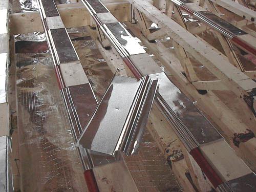
The Aluminum Heat Diffusion Plates
Once the tubing has been threaded through the floor joists, aluminum heat diffusion plates are used to attach it to the bottom of the sub-floor. The plates are made of pure, heat-treated aluminum to make them very malleable like lead sheeting. They are silent, easy to staple to the sub floor and not only hold the tubing securely, but also draw its heat away and spread warmth evenly over the sub-floor. That’s why a close contact between plate and tubing is very important. Recent studies by the American Society of Heating, Refrigerating, and Air-Conditioning Engineers, Inc. (ASHREA), conducted at the University of Kansas, have concluded that heat diffusion plates increase the transfer of heat to the occupied space by almost 175%.
Plating the Radius
While not strictly necessary for most installations, if you’re interested in covering every possible inch of radiant tubing with diffusion plates, Radiant Floor Company offers a special, light gauge pure aluminum plate cut in a triangular shape. These “radius” plates press easily over the tubing, like this:
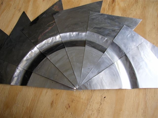
This assembly is upside down, but it demonstrates how the triangles follow the arc around the radius.
Use the heat fins to fasten the PEX tubing to the bottom of the sub-floor. Generally, the plates are stapled with ¼” staples. Ten or twelve staples per plate will work well. Also, try to keep the plates approximately 4″ away from any adaptors or couplings. Run the plates continuously, end to end, along the straight runs of the tubing (not around the radius bends). Keep in mind that running the plates continuously under any floor serves to enhance the overall performance of the system.
Infrared photo of a diffusion plate in action
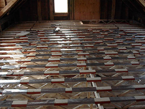
Installing the Radiant Barrier
In all floor joist applications, a reflective barrier is required to direct the infrared heat spectrum up toward the radiant floor. Simple aluminum foil purchased from the supermarket will work, but its tendency to tear and puncture makes it unsuitable for construction purposes. For ease of installation, we recommend a pure aluminum reflective barrier manufactured with embedded poly fibers to resist tearing. Foil faced fiberglass or rigid foam boards are excellent too because they not only reflect the infrared heat, but also add thermal resistance and incline the heat to flow up to the floor. When installing a radiant reflective barrier, always maintain at least 1″ of air space between the tubing and the reflective foil.
When installing a radiant reflective barrier, always maintain at least 1″ of air space between the tubing and the reflective foil.
If the radiant floor is above an unheated basement or crawlspace, insulation is required in order to isolate the heated floor from the colder space below.
Unfortunately, foil faced fiberglass is often very hard to find and foil faced rigid insulation is very expensive. As a result, most people insulate below the radiant tubing in the following manner.
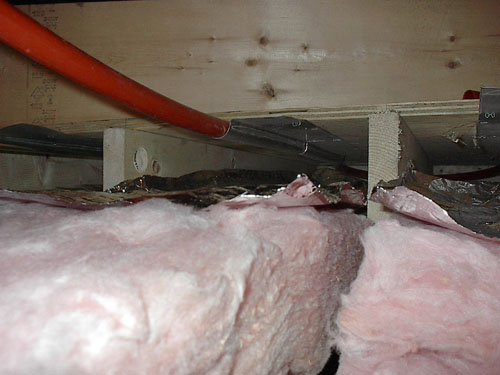
Drop down and install the radiant barrier at least 1″ below the tubing, but ideally no lower than 2″. Fill the rest of the joist bay with insulation. The best way to do this is as follows:
Since the rolls of radiant barrier are 48″ wide, you’ll save a lot of time by clamping the entire roll in a vise, or hanging it over a sawhorse, marking 16″, and cutting the entire roll with a Sawzall or handsaw. Do this twice and you’ll end up with three pre-cut sections, each 16″ wide. Then, simply roll the reflective barrier out to match the length of your fiberglass insulation, lay it on top of the fiberglass so the shiny surface faces the radiant tubing, then push both the insulation and barrier material up into the joist cavity. Just be careful not to push the barrier directly up against the tubing. The 1″ air space is important.
When Running Double the Normal Amount of Tubing Makes Sense
In situations with “fair” or “poor” insulation it may be necessary to run twice the normal amount of tubing. In other words, in the case of 7/8″ PEX (normally run 16″ on center) instead of running one length of tubing per joist bay, the installer will run two. The goal is to end up with the PEX installed 8″ on center, but without exceeding the bending radius of the tubing.
The solution is simple. Run the tubing as you normally would….one length per joist bay…then return to the beginning and repeat the process. Obviously, you’ll be drilling a second set of 1 1/2″ holes fairly close to the ones you’ve already drilled (or perhaps you’ll use a single, larger hole), then feeding your second batch of tubing through. For the second run, you’ll want to mimic the first run as closely as possible in terms of length, of course, because in effect you’re doing nothing more than adding additional circuits and all circuits must be close to equal in length.
When running the second batch of tubing, strive for an approximate 8″ on center spacing, but don’t worry if you have to cross over the first batch of tubing in some spots to achieve this. Attach the tubing to the sub-floor as you normally would using aluminum heat diffusion plates.
Of course, it goes without saying that improving the insulation value of the structure is normally preferable to doubling up on tubing. But sometimes that simply isn’t practical in older buildings. In addition, even modern, otherwise well insulated structures will sometimes require double tubing in certain zones. Because many people take advantage of spectacular views by designing large window walls and high cathedral ceilings, they create an equally spectacular heat loss in these areas. But, then again, nobody is suggesting that we should all live in high R-value caves either. Simply design the radiant system to accommodate the building’s heat loss and all the advantages of light, spaciousness, and comfort can be enjoyed.
Double run of 7/8″ PEX in a 16″ on center joist bay
Installing Radiant Tubing in Structural Trusses
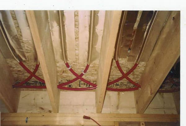
Sometimes it’s necessary or desirable to use trusses instead of standard floor joists. If these trusses are installed over an existing ceiling where access from below is impossible, then the tubing can be fastened to the top edge of the truss as illustrated in the photo below.
The aluminum heat diffusion plates are heat treated to make them very malleable, like lead sheeting. They conform easily to any shape and, unlike aluminum flashing, won’t spring back to their original form. That makes them ideal for many unconventional radiant tubing applications. In this instance they secure the tubing to the top edge of the truss, wrap under the lower lip where they are stapled securely, then bend over the top of the truss where they will later make direct contact with the sub floor.
Using the plate tool provided by Radiant Floor Company, the heat diffusion plate is formed with the tubing channel offset three inches from the edge. This provides a lip for stapling along the bottom edge of the truss, a cradle for the tubing, and still allows the bulk of the plate to cover the top of the truss and transfer heat directly to the sub floor.
Because the tubing in this type of application is, by necessity, installed before the finished hardwood floor, it’s very important to snap chalk lines onto the sub floor while it is being installed. The chalk lines indicate the exact center of the truss so that later, when the hardwood is nailed down, all floor nails follow the chalk line and stay clear of the tubing.
These 9″ trusses are insulated from the floor below with 6″ of fiberglass that has been covered with a layer of radiant reflective barrier. This guarantees that the radiant heat will flow up into the newly remodeled master bedroom.